Tips and Tricks
Advanced Searching of the MSO CHM Help File
Despite the antiquated nature of Microsoft's reader for compiled HTML help (.CHM) files, its search function is surprisingly feature-rich. For instance, if you wish to find information about negative delay values and how to deal with them, click the Search tab of the help file reader and enter "negative delay" (including quotes). The presence of the quotes indicates that you wish to search for the phrase with both words together, not just the individual words.
When the help reader finds one or more matches, they'll show up in a list under the search box. Double-click the list item to go to the matching page. Unfortunately, to go to the actual matches, you'll need to first click on the matching page on the right, then press Ctrl+F and enter the search text again.
While this isn't a perfect situation, it can be surprisingly effective and is much less time-consuming than trying to search the MSO web pages.
Search syntax includes not only searching for phrases as mentioned above, but also wildcard search and logical operators such as AND, OR, NOT, and NEAR. Documentation of this syntax is available on a very useful web page by Microsoft MVP Robert Chandler. It's well worth a read.
Configuring Windows to Always Show Alt Shortcuts Underlined
Old-timers may remember that early versions of Windows always showed characters associated with Alt-key shortcuts in menus and dialog boxes with those characters underlined. At some point, they changed this behavior so these characters were only shown underlined after pressing the Alt key. You can restore the original behavior using the following steps.
-
For Windows 11:
- Open the Settings app.
- Choose Accessibility.
- Under Interaction, choose Keyboard.
- Set Underline access keys to On.
-
For Windows 10:
- Open the Settings app.
- Choose Ease of Access.
- Select Keyboard in the left pane.
- Scroll down to find Change how keyboard shortcuts work in the right pane.
- Enable Underline access keys when available.
Copying and Pasting Filters
You can copy filters in the following ways:
- Copy all filters in a channel by selecting its Filters node in the Config View and pressing Ctrl+C.
- Copy selected filters of a channel by selecting its Filters node in the Config View and pressing Ctrl+Shift+C.
- Copy a single filter by selecting the filter itself in the Config View and pressing Ctrl+C.
In combination with the filter paste feature, this is a quick way to add many filters to one or more channels of a configuration. If you choose to copy selected filters of a channel, a dialog box pops up listing the filters in the channel, with a check box next to each one. You can then paste them into the same channel or a different channel of any configuration by using Ctrl+V. When pasting filters to a destination channel, sometimes not all filters will be pasted. This can occur if e.g. you try to paste delay blocks, gain blocks or LPFs to a main channel, or if the paste operation would result in too many delay or gain blocks in a sub channel. If not all copied filters are pasted to the destination channel, a tabbed text view is created, listing the filters that weren't pasted and why. This is to show what happened without a dialog box getting in the way. The information in this text view is temporary and not saved with the project.
You can also copy filters to another project if desired. To do this, just copy the filters you want, close the project, then open a different one. The filters are still in the clipboard, and so they can be pasted into the newly-loaded project.
The copy and paste commands appear on the edit submenu of the main menu, on context menus in the Config View, and on toolbar buttons. You can see whether the copy or paste commands are available by looking at the appearance of the copy and paste toolbar buttons. If the copy or paste command is enabled (meaning the cursor is on an appropriate node of the Config View), the buttons will show in color. If not, they will display in gray scale. The logic of whether filter paste is enabled is more complex than it first appears. If you have copied e.g. only a delay and a gain block to the clipboard, and you move the cursor to a main channel filter node with the intent of pasting the filters to the main channel, the paste command will be shown as disabled, as neither delay nor gain blocks are allowed in a main channel. To paste the filters using the Ctrl+V keyboard shortcut, be sure the focus is on the Filters node of the desired destination channel in the Config View and not one of the tabbed views on the right.
For additional information about copying and pasting filters, see the Adding Multiple Filters Using Copy and Paste subtopic of the Creating Specialized Configurations topic in the Tech Topics section.
The Different Methods of Specifying Filter Parameter Values and Limits
It's useful to understand the different methods MSO makes available to you to specify filter parameter values and their allowable limits. Each one is applicable under different circumstances. Some of these methods require a pre-existing filter whose parameter properties need adjustment, while another affects only filters that have yet to be created. Some methods only affect allowable parameter limits without affecting parameter values, while another does the exact opposite, and yet another allows specifying both parameter values and their limits.
These methods are summarized below.
- You can choose Tools, Application Options, Filter Parameter Defaults from the main menu to specify the default parameter limits of newly-created filters.
- You can select an existing filter in the Config View and alter its parameter values and limits in the Properties Window on the right side of the main window.
- Using the Sub General PEQ Limits and Sub Input PEQ Limits property pages of the Optimization Options property sheet, you can specify the allowable parameter limits of all pre-existing sub PEQs of a given configuration.
- Using the Main Speaker General PEQ Limits and Main Speaker Shared PEQ Limits property pages of the Optimization Options property sheet, you can specify the allowable parameter limits of all pre-existing main speaker PEQs of a given configuration.
- Using the Sub Output APF Limits property page of the Optimization Options property sheet, you can specify the allowable parameter limits of all pre-existing sub output all-pass filters of a given configuration.
- By choosing Config, Reset All Filter Parameter Values from the main menu, you can reset all the filter parameter values of a configuration back to their defaults.
Using Application Options to Set Default Filter Parameter Limits
You can specify the default filter parameter limits for a large variety of filter types by choosing Tools, Application Options, Filter Parameter Defaults from the main menu. The Parametric EQ property page of this property sheet is shown below.
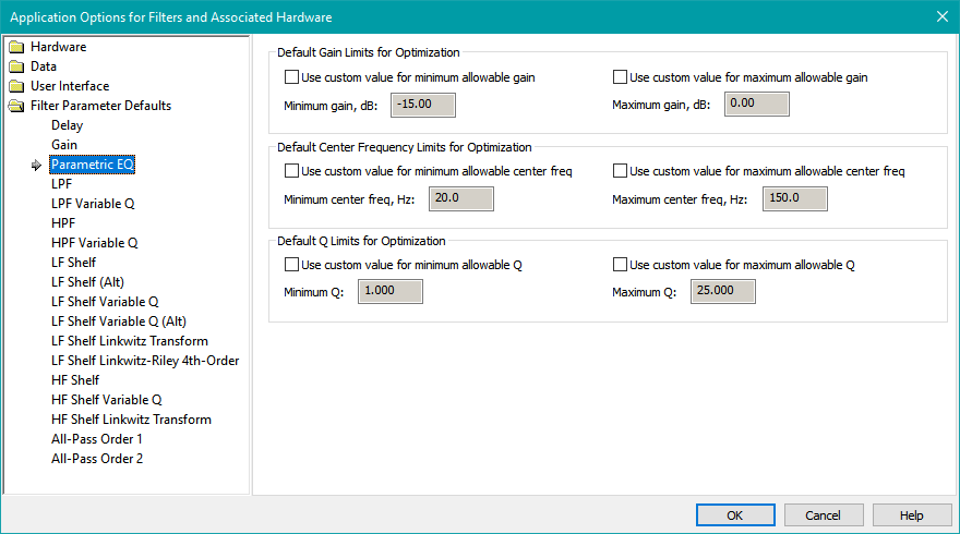
Each category of filter has its own property page for setting its allowable parameter value limits. The purpose of these property pages is primarily so that when you create new filters using a context menu, or when MSO creates them for you in the Configuration Wizard, MSO will create them with parameter limits that are compatible with what the hardware allows. This is best illustrated by a concrete example.
Suppose you are using a Behringer DSP amplifier. These amplifiers support PEQ filters, but the PEQ filters you create must have a Q value not greater than 10. If you're using one of these Behringer amplifiers, you should choose Tools, Application Options, Filter Parameter Defaults, Parametric EQ from the main menu to set the maximum allowable Q value to 10 before running the Configuration Wizard. Then, when you run the Configuration Wizard, the parameter value limits of the PEQs that MSO creates for you will be compatible with the Behringer amplifier.
Since the filter parameter values of miniDSP hardware are most conveniently specified by using biquad file import, the Tools, Application Options, Filter Parameter Defaults property sheet will seldom be used with such devices. Since specifying biquad coefficients allows for a huge variety of filter types and their parameter values, you won't run into a situation where MSO creates filters that can't be implemented by the miniDSP devices. However, there is a related usage of these property pages that is still applicable: preventing MSO from creating filters whose parameter values are simply not realistic. For instance, the miniDSP 2x4 HD units have a range of allowable delay values that extends to 80 msec. This corresponds to a distance of about 90 feet. This is clearly excessive, so it makes sense to limit the delay to a more sensible range using this property sheet.
Note that the filter settings of the Application Options, Filter Parameter Defaults property pages change only the default filter parameter limits for newly-created filters. This property sheet does not affect parameter limits of existing filters, nor can it be used to specify default filter parameter values.
Controlling All-Pass Parameter Limits Set by the Configuration Wizard
Beginning with MSO 2.3, you now have control over the default parameter limits for all-pass filters set by the Configuration Wizard. This is done using the Application Options property sheet. From the main menu, select Tools, Application Options. Under Filter Parameter Defaults, choose either the All-Pass Order 1 or All-Pass Order 2 property pages. The property page for All-Pass Order 2 is shown below.
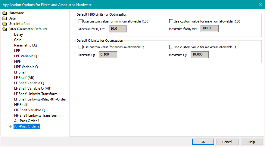
First, select the checkboxes for all the parameters you'd like to set custom limits for. Enter the desired limits, then check the Use these values in the Configuration Wizard checkbox. When this checkbox is checked, the Configuration Wizard will use these limit values as defaults when creating all-pass filters for the configuration (should you choose to use them).
Modifying Individual Filter Parameter Values and Limits Using the Properties Window
When a filter is selected in the Config View, the Properties Window on the right side of the main window will show information about the filter, its parameter values, and the upper and lower limits of permissible values of each parameter. This is illustrated below.
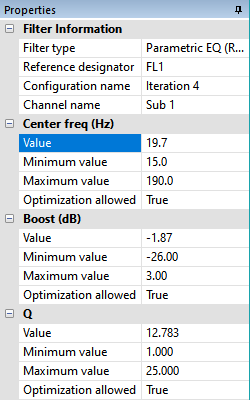
The first group of properties is Filter Information. You can't alter any of the Filter Information values as their purpose is just to identify the filter, its type, and other information about it.
After the Filter Information fields are the parameters. Each parameter has four properties as follows:
- The parameter Value, which under normal conditions is adjusted by the optimizer during an optimization.
- The parameter Minimum value, which is the lowest value that the Value property is allowed to take on when being adjusted by the optimizer during an optimization.
- The parameter Maximum value, which is the highest value that the Value property is allowed to take on when being adjusted by the optimizer during an optimization.
- The parameter Optimization allowed, which is a Boolean property that determines whether the optimizer is allowed to alter the Value property of the parameter during an optimization.
Only the information in the right column of the Properties Window can be changed. You can change the parameter properties in the right column by editing them as you would in a spreadsheet, by using the F2 shortcut key. In addition, when you click in the right column of the Value property of a parameter, a spin control with up and down arrows appears, allowing you to tune the value by pressing either of these two arrows.
If the Optimization allowed property of a parameter is set to False, the parameter will retain its value as set in the Properties window and it won't be changed by the optimizer. Such a parameter is said to be locked. If all the parameters of a filter are locked, the filter icon in the Config View will be a dark gray color, indicating that the optimizer can have no effect on the filter at all. Only manual changes via the Properties window are allowed for such filters. If some, but not all the parameters of a filter are locked, the filter icon in the Config View will be a light gray color. If a filter has no locked parameter, its Config View filter icon will be white in color.
Setting Parameter Limits For Groups of Filters of a Configuration
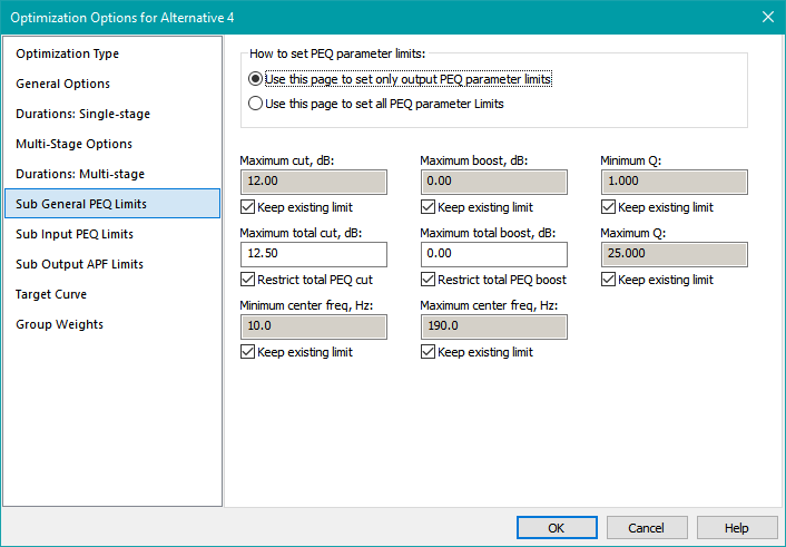
You can set parameter limits for groups of PEQs and, if present, all-pass filters of a configuration. For subs, this is accomplished using the Sub General PEQ Limits, Sub Input PEQ Limits and Sub Output APF Limits property pages of the Optimization Options property sheet. The Sub General PEQ Limits property page is shown below.
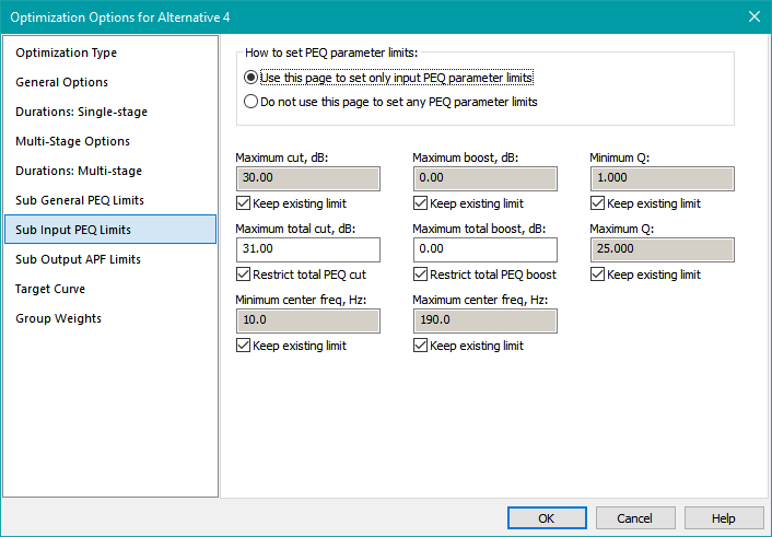
The Sub Input PEQ Limits property page is shown below.
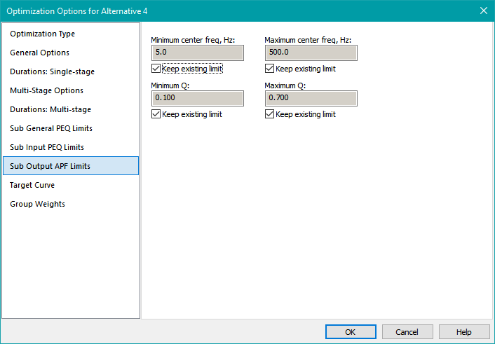
The Sub Output APF Limits property page is shown below.
The methods you can choose for setting groups of filter parameter limits are described in detail in the Property Pages for Setting Filter Parameter Limits reference material, so they won't be discussed further here.
Resetting All Filter Parameter Values of a Configuration to Their Defaults
In certain situations, it's very useful to be able to manually reset all parameters of all filters of a configuration to their default values at once. For instance, the default state of PEQ filters is a flat response (0 dB gain at all frequencies). If the only frequency-shaping filters of a configuration are PEQs, then setting all filters to their default state is the same as restoring the state of a configuration to what it was before optimization.
In other situations, you might want the optimizer to automatically reset the filters of a configuration to their default state before running the optimization. Certain optimization types will use the current values of all filter parameters as a starting point. If the current filter parameter values are all near their optimum, the optimizer can appear to be "stuck", even if it's steadily improving its collection of trial solutions, but has not yet improved on the best one. By resetting the filter parameter values to their defaults first, the optimizer starts with a large error, and you can see it steadily improving the solution from the start.
Resetting Filters Manually
There are two ways to manually reset filter parameters to their defaults.
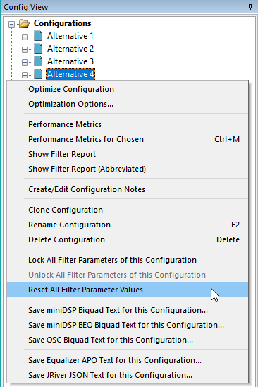
- In the Config View, right-click on the configuration whose parameters you wish to reset, and choose Reset All Filter Parameter Values.
- From the main menu, choose Config, Reset All Filter Parameter Values. This will launch the Filter Reset Dialog.
The technique using the context menu is shown below.
The Filter Reset Dialog that's launched from the main menu is shown below.
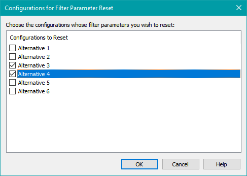
This allows you to reset all the filter parameters of multiple configurations at once. Use care when invoking this command.
Performing a manual filter reset is useful when you want to create comparison graphs of data before and after optimization. If you only have configurations that have already been optimized, you can clone one of them, call the clone Baseline, then perform the Config, Reset All Filter Parameter Values on it to set it back to the pre-optimization state. Then you can create a comparison graph to see the effect of optimization.
Resetting Filters Automatically Before Optimizing
For detailed information on this topic, see Automatically Resetting Filter Parameters to Their Defaults in the Optimizing a Single Configuration subtopic of Running an Optimization.
Guidelines for Setting Delays and PEQ Parameters
The following sections contain some guidelines for avoiding errors when determining sub delays and setting the limits of PEQ center frequencies.
Avoiding Excessive Delays of Individual Subs
The DSP hardware that's most commonly used with MSO is the miniDSP 2x4 HD. This device gives you the ability to set far larger sub delays than are needed in any home environment. One way to see this is to take its maximum delay and convert that to a distance, corresponding to an anechoic environment. In such an environment at a typical room temperature, the 80 msec maximum delay of this device corresponds to a distance of about 90.1 feet. This is larger than would ever be needed in even the most extreme home theater setups. For this reason, the maximum allowable delay of MSO delay blocks for individual subs should be much less than this 80 msec maximum value. The Configuration Wizard sets the allowable range of the delay blocks it creates to 0±20 msec.
When DSP maximum delay values are converted to distance in this way, the distance numbers obtained should be interpreted as the difference in distance to the measurement position of the most distant sub and the closest one. These distances are usually measured to the MLP.
Should Sub Delays Be Determined Based Only on Distances?
One way to estimate each delay is to use the procedure in AustinJerry's guide called "Using MiniDSP 2x4 to Time-Align Multiple Subs on One Channel before Room Correction". Although AustinJerry's guide does not explicitly state this, it makes the implicit assumption of an anechoic environment for its calculations.
Why can this be called an "implicit assumption of an anechoic environment"? It is because an anechoic environment only contributes a delay to each sub's acoustically measured phase shift. The delay introduced to each sub's measured response in an anechoic environment can be computed precisely from the distance of that sub to the measurement position.
In a real-world environment where room modes dominate, this assumption breaks down, and the errors caused by the assumption can be significant. If the assumption were true, it would always be possible to obtain perfect "time alignment" between subs using this distance-based technique. This in turn would mean that if you were to use the REW Alignment Tool, you would never be able to improve on the results of the distance-based calculations. However, it's actually quite rare for the usage of the REW Alignment Tool to not result in improvements.
That said, the distance-based delay calculations provide some common-sense guidelines for what approximate delay values should be used. For instance, you don't want to be adding delay to a sub that's significantly further away from the MLP than all the others. On the other hand, the delays computed from distance are often treated as sacrosanct, such that if software computes different delays, it must be a bug. The "bug" here is in the false assumption.
MSO does not adjust sub delays based on the anechoic assumption of distance-based calculations. Instead, it adjusts delays based on frequency-domain considerations, taking room modes into account. Therefore it's common for the actual delay computed by MSO to be significantly different from the delay computed by only using distances. This means the computed delay could be larger than the result of distance-based calculations. But how large a maximum delay should be allowed, and what should the actual delays be, given that room modes affect the delay values that MSO calculates?
Getting Optimum Delays With Sub-Only Configurations
Fortunately, new optimization methods beginning with MSO v2 provide an answer to the optimum-delay question. To understand why requires a brief comparison of legacy MSO optimization methods with some new ones introduced in MSO v2.
The most common optimization method used in MSO v1 (and still available in MSO v2) is called Minimize seat-to-seat variations (STSV) and flatten MLP response. The STSV and MLP flatness are the only parameters optimized using this approach. As such, the per-sub delays computed by MSO only take into account these two errors. In the past, this has sometimes resulted in solutions that have delays far different from what is expected. Various ad hoc techniques have been used to prevent this.
MSO v2 provides structured techniques that address this problem. These consist of two new optimization methods: Maximize SPL using only delays and all-pass filters and Multi-stage: Maximize SPL, minimize STSV and flatten MLP response. Why would optimization methods that maximize SPL result in optimum delays? That's because SPL maximization attempts to get all subwoofers acoustically in phase with each other at all frequencies in the SPL optimization range and at all listening positions.
Let's look at a hypothetical case of a perfect anechoic environment with only a single measurement position and with two identical subs having different distances to the measurement microphone. In this case, "time alignment" would force the acoustical outputs of both subs to be in phase with each other at all frequencies. SPL maximization does the same thing. Now suppose that instead of using two identical subs, one sealed and one ported sub were used. Even in this perfect anechoic environment, and with no other changes, SPL maximization would give slightly higher overall SPL than "time alignment" because it's matching phase. If one were to add an all-pass filter with optimizable parameters to the signal path of the sealed sub, SPL maximization would give significantly higher overall SPL, especially at the lowest frequencies where it's most critical.
Thus SPL maximization can be thought of as a kind of generalized "time alignment" that takes into account both room modes and non-identical subs. It solves the problem of delay optimization for a broad range of situations.
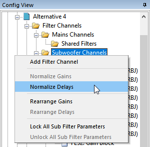
Normalizing Delays
The Normalize Delays command ensures that all per-sub delay blocks have a delay that is positive or zero. To normalize delays, go to the Config View and right-click on the Subwoofer Channels node for the desired configuration. Choose Normalize Delays as shown below.
For sub-only configurations, no shared delay block is allowed, but Normalize Delays still works by adding the appropriate and identical delay to each sub channel so that one individual sub delay is zero and the rest are positive. This can be done because only the subs' relative delays matter in a sub-only configuration. This command can result in one of the per-sub delay blocks shifting from one channel to another, so in connection with allowing negative per-sub delays, the command can be used to determine which individual sub channel should end up with no delay block. This is done by running an optimization, then performing the Normalize Delays command afterwards. You can also find out which sub ends up with zero delay without having to run a Normalize Delays command. If you have already optimized the configuration, open up a filter report for it and scroll down to the end. You'll see it under Delay settings.
For subs+mains configurations, this command eliminates negative delays for individual subs by lumping them all into a shared delay block. A negative delay in a shared delay block corresponds to a required increase of AVR sub distance relative to its value when the measurements were performed. You can determine the amount of this distance change if the option System uses AVR or pre-pro with sub out is checked in the Hardware, Filter Reports property sheet of the Application Options dialog. See the filter report page of this reference manual for an illustration of this dialog. To determine the required change of AVR sub distance setting corresponding to this shared delay, open up a filter report for the configuration in question and scroll down to the end. You'll see it under Final gain and delay/distance settings.
Setting the Center Frequency Range for PEQ Filters
The center frequency range you assign for PEQ filters should be based on the minimum and maximum optimization frequencies you choose on the General Options property page of the Optimization Options property sheet. You'll need to set the allowable center frequency range of the PEQ filters so the optimizer can do its job over the full frequency range you've specified. Guidelines for setting the PEQ center frequency range are as follows.
-
For sub-only configurations:
- Set the minimum and maximum PEQ center frequencies to be the same as the minimum and maximum optimization frequencies respectively.
-
For subs+mains configurations:
- For subwoofers, set the minimum PEQ center frequency to the minimum optimization frequency. Set the maximum PEQ center frequency to twice the highest anticipated crossover frequency or the maximum optimization frequency or 200 Hz, whichever is smallest.
- If the main speakers have PEQs, set the maximum PEQ center frequency to the maximum optimization frequency. Set the minimum PEQ center frequency to one-half the lowest anticipated crossover frequency.
Saving Graph Traces as Text Files
You can export any trace to text format for import into other programs. To save a graph trace as text, perform the following steps:
- In the Data View, go to the desired graph and expand its tree node as necessary to show the nodes (folder icons) that represent individual traces.
- Right-click on the node of the trace whose data you wish to export, and choose Save Trace as Text from the context menu. See the figure below.
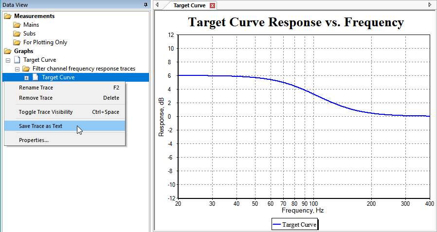
Starting with MSO v2, this is the "official" method to export complex target curves. See the target curve example for details.
How Many Subs are Needed?
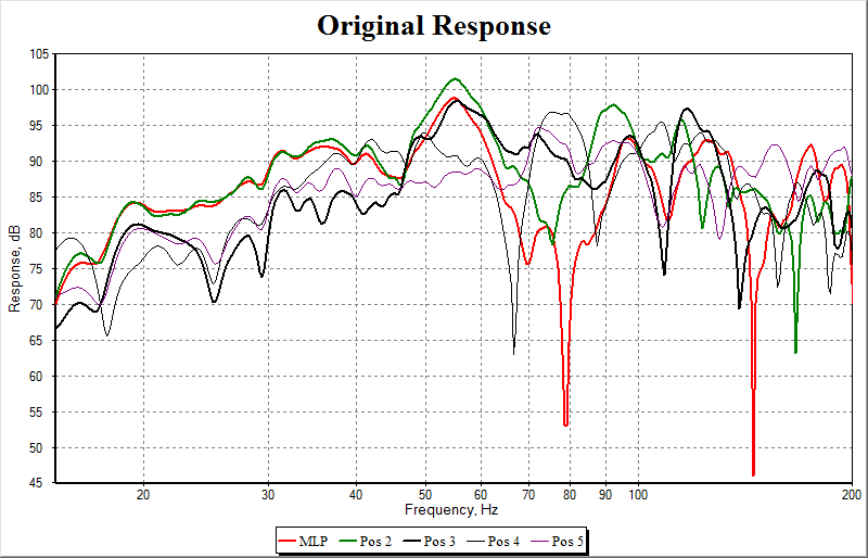
Early versions of the MSO documentation suggested that three or more subwoofers might be needed to get significant measurable improvements with MSO. User experience has subsequently shown that MSO can provide good improvements for two-sub systems as well. The AVSForum user genesplitter has posted his MSO results with a two-sub system at five listening positions. These are summarized below.
First, the data before using MSO:
Next, the data after using MSO:
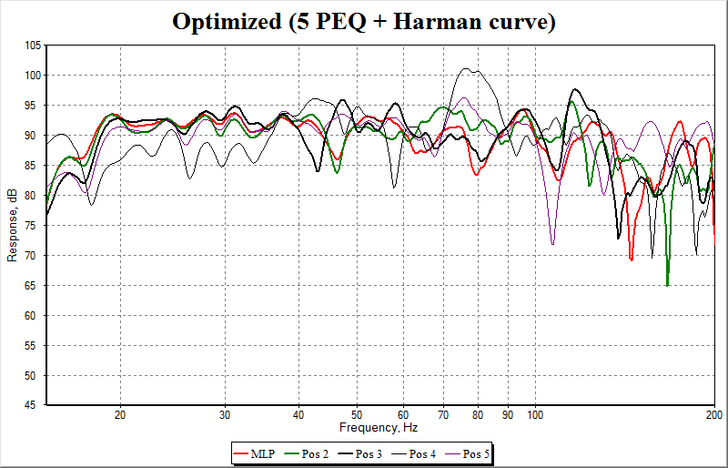
Substantial improvements have been made at all listening positions. Based on this information, usage of MSO can be recommended for systems having two or more subwoofers.