Gathering Filter Information
Using Biquad Export and Filter Reports
Once you've decided on a configuration to use, you'll need to gather that configuration's filter parameter information for entry into your DSP device. The method for doing this varies with the type of DSP device you're using. These devices fit into one of two broad categories listed below.
-
The best DSP devices for use with MSO nowadays are those that support biquad text file import. These include devices from miniDSP and QSC. For these devices, you export biquad text files from MSO and use the device's associated software to import the files. This is done in accordance with the following procedure:
-
Export the filter data for the configuration in biquad text format.
- This creates a biquad text data file for each channel.
- Import the biquad filter text data for each channel into the appropriate channel of the device.
- Generate an MSO filter report. The required gain and delay values for each channel are listed at the end of the report.
- Manually enter the delay values found at the end of the filter report into each channel of the device.
- If you are using per-sub gain blocks (not recommended), manually enter the gain values at the end of the filter report into each device channel.
-
Export the filter data for the configuration in biquad text format.
-
Devices from other vendors without biquad support require a purely manual data entry approach. This consists of the following:
- Generate an MSO filter report using the abbreviated option. This option minimizes filter report clutter.
- For each channel listed in the filter report, manually enter the parameters for each filter of that channel.
- Manually enter the gain and delay values found at the end of the filter report into each channel of the device.
More detail is provided in the following sections.
Specifying Hardware Properties
Before you enter any biquad data into your DSP device, you'll need to give MSO some information about its capabilities so the files it exports will be compatible with it.
To specify information about your DSP device, choose Tools, Application Options from the main menu, then click on Biquad Properties to show the Biquad Properties property page.
If you are using MSO to integrate subs and mains via a "subs+mains" configuration (not common), you'll also need to specify some properties of your AVR by choosing Tools, Application Options from the main menu, then clicking on AVR Properties to launch the AVR Properties property page.
These two property pages are described below.
The Biquad Properties Property Page
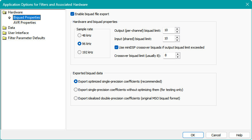
The image below shows the Biquad Properties property page.
Enabling Biquad File Export
This option is unchecked by default when MSO is first installed. When unchecked, all biquad export menu items, both in context menus of the Config View, and the dropdown menu of the Config main menu item will be disabled. This is because using a default biquad configuration for hardware whose properties do not match those defaults can result in substantial errors that are difficult and time-consuming to diagnose, especially for new users.
Once Enable biquad file export is checked, all controls of this property page will be enabled, as well as the corresponding export commands in the context menus of the Config View and the Config dropdown of the main menu. The settings specified on this property page are all stored in the Windows registry, not the project, so they persist across projects. For this reason, if you move a project from one machine to another, you should make sure these settings are all correct on that machine.
After checking this checkbox, all other controls of this property page will be enabled. You must set these to the correct values for export of biquads from MSO and import into your DSP device to be successful. The default values of the control data are set to match the miniDSP 2x4 HD device.
Setting the Device Sample Rate
It's absolutely essential to select the correct sample rate here, or else the actual filters loaded into your hardware will have a frequency response that doesn't resemble the prediction at all. The default value of 96 kHz is correct for the miniDSP 2x4 HD device. Be careful with this setting, as some devices have different firmware flavors available, with different sample rates for different firmware flavors. In such cases, look up your device and firmware specifications to find the correct sample rate required for the firmware flavor you're using.
Setting the Device Biquad Limits
The options for the values of the various device biquad limits are chosen so that you can take the fullest possible advantage of your hardware's capabilities, while at the same time preventing MSO from saving biquad files that are incompatible with your hardware.
For compatibility with the miniDSP 2x4 HD device, enter a value of 10 for the input and output biquad limit as shown in the illustration above. For other miniDSP devices, check the documentation for the device and its firmware.
Extending the Biquad Limits Using Crossover Biquads
With miniDSP devices, you can make use of 8 more biquads per channel than would otherwise be available by choosing the Use miniDSP crossover biquads if output biquad limit exceeded option. One biquad corresponds to one PEQ. As a specific example, the miniDSP 2x4 HD can use up to 10 PEQs per output channel in a normal setup. You can increase this to 18 PEQs per channel by using the Use miniDSP crossover biquads if output biquad limit exceeded option. In this case, if your MSO configuration uses, say, 15 PEQs per sub, when exporting biquad text you will get two biquad files per channel: one for the output channel and a second for the crossover of that channel. If your output channel biquad text file were named e.g. "chan1.txt", the crossover biquad text file would be named "chan1_xo.txt". For this specific example, the crossover biquad text file would contain the biquads for 8 PEQs, while the output channel biquad text file would contain the biquads for 7 PEQs (since we assumed 15 PEQs per sub were to be used). For more information on this feature, see Extending Filter Capacity by Using Crossover Biquads on this page.
Setting the Exported Biquad Data Format
When specifying the exported biquad data format, you have three options:
- Export optimized single-precision coefficients
- Export single-precision coefficients without optimizing them
- Export idealized double-precision coefficients
Usage of these options is described below.
- The Export optimized single-precision coefficients option is recommended unless you have a specific reason for not using it. See the backstory explanation below for how these options came about. When you load these coefficients into the miniDSP Device Console, it will accurately show the actual filter responses you'll achieve in practice.
- Use Export single-precision coefficients without optimizing them if you want to use the miniDSP Device Console to see what the channel responses would look like without coefficient optimization.
- Use Export idealized double-precision coefficients if you want to load the coefficients into the miniDSP Device Console to compare the responses using the optimized single-precision coefficients with the idealized responses to check if the optimization is working as intended.
The Backstory of the Biquad Export Options
These options arose from some recent studies regarding filter inaccuracy at frequencies below about 30 Hz. These inaccuracies, which can be surprisingly large for certain unpredictable combinations of filter parameters, result from the finite precision of the biquad coefficients in the DSP chips that implement the filters. These chips implement the filters using 32-bit single-precision floating-point coefficients. The behavior of such floating-point numbers is exhaustively described in a specification called IEEE-754.
To make a long story short, these recent filter studies found that for many of the most problematic filters, the inaccuracies could be almost entirely eliminated by performing an optimization on the filter coefficients. This optimization makes very small changes to the coefficients in such a way as to make the response of the actual filter match that of the ideal filter almost exactly in many cases.
These optimizations aren't perfect though. Experiments suggest that the ability of the optimization to correct rogue filters begins to degrade rapidly for PEQs with center frequencies below about 15 Hz when a 96 kHz sample rate is used. Lower sample rates such as 48 kHz give superior results for subwoofer applications at the lowest frequencies.
At present, these optimizations are only implemented for PEQ filters (both of the legacy and RBJ types). Coefficient optimizations for more filter types are planned for future MSO versions.
The AVR Properties Property Page
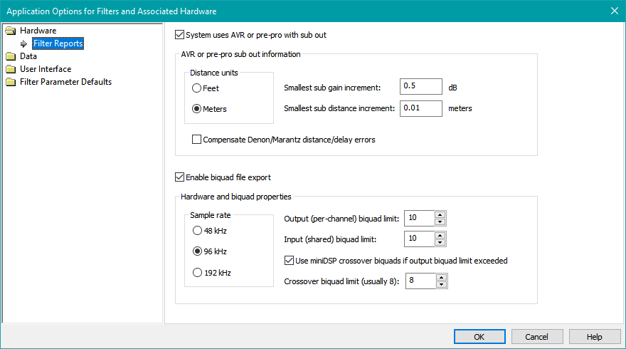
The AVR Properties property page is shown below.
Specifying AVR Sub Out Properties
Checking System uses AVR or pre-pro with sub out is only necessary when using a "subs+mains" configuration. For such configurations, MSO reports the required AVR final sub distance and trim values using the distance and gain step resolutions you specify.
The AVR or pre-pro sub out information options shown above are typical settings. The units for distance setting are configured to use feet, and the smallest sub distance increment is set to 0.1 feet. These options are provided so that MSO can tell you how much to change your AVR's sub distance setting after an optimization (if applicable). Also, MSO tries to fine-tune the DSP delay settings to make up for the limited delay resolution of a typical AVR, so that the actual delays of your system after data entry are as close as possible to what MSO calculates. A similar situation applies to the AVR sub gain adjustment resolution (Smallest sub gain increment) specified here. MSO tries to fine-tune the DSP gain settings to make up for the limited resolution of the AVR sub level adjustment.
The Denon/Marantz Distance/Delay Error Bug
The Compensate Denon/Marantz distance/delay errors option causes MSO to take certain erroneous delay vs. distance calculations in older Denon and Marantz AVRs and pre-pros into account when calculating sub distance.
Older Denon and Marantz AVRs and pre-pros had a bug that resulted in incorrect conversions between speaker distances and delays. This bug was first reported by Steve Easley in the AVS Forum thread titled "Audyssey time alignment is off according to REW impulse readings?" This error was verified by others in the thread, including the user of a Denon AVR-4308 (a 2008 model) and a Denon CI-3312 (a 2012 model). The most recently introduced D&M AVRs have supposedly fixed the error. Check on the forums for whether your AVR contains the fix. Results of measurements of older AVRs show that the error has been present for quite a long time. Audyssey apparently knows about this and compensates for it in its MultEQ-X application when needed.
Note: According to an article on the Audyssey web site dated January 2023, the problem was limited to AVRs "before 2022 models", although specific model numbers aren't mentioned.
Although the specific implementation details of this bug can't be known, a number of conclusions can be drawn from the measured data taken so far.
- The delay resolution is nominally 0.1 msec, regardless of whether the distance mode is set to feet (with 0.1 foot resolution) or meters (with 0.01 meter resolution).
-
The nominal distance units of feet and meters might be better described as "fake feet" and "fake meters" respectively.
- One nominal foot corresponds to 1 msec delay, so that the 0.1 foot increment corresponds to 0.1 msec delay. Since the actual speed of sound is 1126 feet/sec (dependent somewhat on temperature) and not 1000 feet/sec, nominal feet do not correspond to actual feet and so might be better described as "fake feet".
- When distance mode is set to meters, there are conversions between meters and feet that do not agree with the real-world unit conversions between meters and feet, and the computed speed of sound in nominal meters per second thus obtained does not agree with the actual speed of sound in real meters per second. Therefore, the actual distance units in this mode might be called "fake meters". The distance increment of 0.01 nominal meters or 1 nominal cm might be better described as "fake cm".
-
When the distance mode is set to meters with a distance increment of 0.01 meters, the minimum distance increment is 1 "fake cm". This distance in "fake cm" can always be represented as an integer. To get delay in msec from the "fake cm" value, the following algorithm accurately replicates the actual measured delay data.
- Convert the integer "fake cm" to "fake feet" by multiplying by 0.1 / 3.
- To replicate the actual measured data, perform this conversion by doing an integer division by three first, giving truncation (not rounding) of the integer quotient, then multiplying the resulting integer by 0.1. The result will always be an integer multiple of 0.1 "fake feet", and the nominal delay in msec will also be equal to this "fake feet" value.
- This integer division by 3 always results in 3 consecutive "fake cm" values yielding the same delay value, so the actual delay resolution is about 3 times worse than the nominal distance resolution of 1 cm suggests.
- Accuracy of delay is also impacted by the sample rate, which is 48 kHz when Audyssey is on. All delays must end up as an integer number of samples. A 48 kHz sample rate gives 48 samples per msec, which, by the Denon/Marantz conversion is 48 samples per "fake foot". However, the distance resolution is 0.1 "fake feet", which is intended to equate to 0.1 msec. A single 0.1 msec delay corresponds to 4.8 samples. All delays are rounded to integer multiples of 0.1 msec, say (N * 0.1) msec, so the final computed number of samples to achieve this delay must be rounded to the nearest integer to (N * 4.8) samples.
- The source code of a simple C++ console-mode program that implements this algorithm, along with a table showing computed delays vs. distance in 0.01 "fake meters" increments, can be found here. These computed delays have been shown to match measured delays taken at line level using a Denon CI-3312 AVR to within 0.0001 msec (0.1 microseconds) for all delays measured so far.
Listing Filter Information in a Filter Report
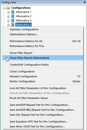
At any time, you can see a summary of the parameter values of all filters in a configuration by choosing Config, then Show Filter Report from the main menu. This will list all parameter values for all filters of the chosen configuration in a tabbed text view. This can also be done by right-clicking on the root node of a configuration in the Config View and choosing Show Filter Report. Use the Abbreviated option as shown in the image below to minimize clutter in the filter report.
Contents of the Filter Report
A tabbed text view with filter information will appear as in the figure below.
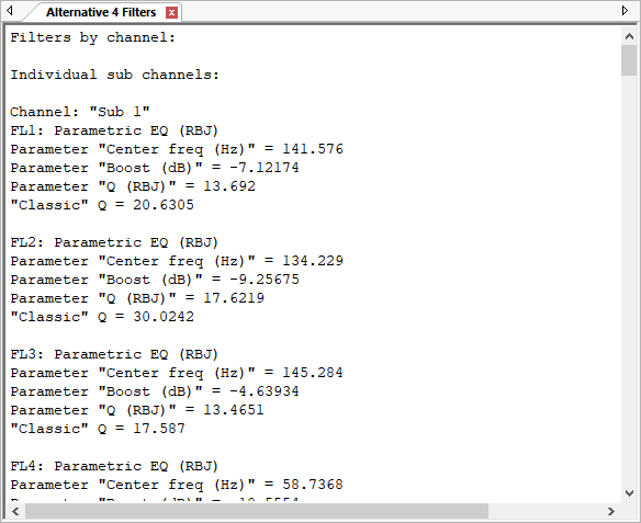
The filter report data shows all parameters of all filters, grouped by filter channel to help with data entry into hardware such as the Behringer DSP amps. For these amps, you'll need to enter the data manually using the application they provide. For information about compatibility of Behringer DSP devices with MSO's filter types, see the Behringer compatibility section.
The Final Gain and Delay Values
Even if you're using biquad text export from MSO for import into a miniDSP device, you'll still need to enter MSO's calculated delay and gain values manually. This information is gathered at the end of the filter report. The quickest way to access it is to click in the filter report window, then press Ctrl+End. You'll see something like the text shown below.
Final gain and delay/distance settings:
---------------------------------------
Gain settings:
Sub 1 gain: 0.00 dB
Sub 2 gain: 0.00 dB
Sub 3 gain: 0.00 dB
Sub 4 gain: 0.00 dB
Delay settings:
Sub 1 delay: 0.00 msec
Sub 2 delay: 11.72 msec
Sub 3 delay: 10.20 msec
Sub 4 delay: 18.14 msec
Channel inversions:
No inversions
Shown above is the information for a sub-only configuration. Only the Gain settings and Delay settings need to be set. For subs+mains configurations, the information is similar, except that AVR sub distance and gain trims are added.
Final gain and delay/distance settings:
---------------------------------------
Gain settings:
Increase AVR sub out trim gain by 1.50 dB
Sub Channel 1 gain: -5.63 dB
Sub Channel 2 gain: -0.07 dB
Sub Channel 3 gain: -14.09 dB
Sub Channel 4 gain: -4.23 dB
Delay settings:
Decrease AVR sub out distance by 3.00 feet
Sub Channel 1 delay: 12.35 msec
Sub Channel 2 delay: 4.54 msec
Sub Channel 3 delay: 4.46 msec
Sub Channel 4 delay: 0.05 msec
Channel inversions:
No inversions
In the latter example, small gain and delay tweaks are enabled in the miniDSP to make up for the AVR's sub gain and sub distance adjustment resolutions respectively.
Using Biquad Export Support
You can export biquad text files in MSO using two categories of techniques. You can either export them all at once for all channels of a configuration, or you can export them on a channel-by-channel basis. Within each of the two categories, there is more than one method to perform the export in the UI. These methods are described below.
Exporting Biquad Text of All Channels of a Configuration
The easiest way to export biquad text for the miniDSP is to do so for all channels at once. In that case, you end up choosing a destination directory for the files, and the names of all the biquad text files are created for you automatically. This approach requires the least amount of effort. There are two ways to export biquads for all channels in the UI: using the main menu or a context menu in the Config View.
Exporting Biquad Text of All Channels Using the Main Menu
To export all biquad text of a configuration using the main menu, use the Config submenu. Choose Save Config to miniDSP Biquad Text Files as shown below for miniDSP devices, or Save Config to QSC Biquad Text Files for QSC devices.
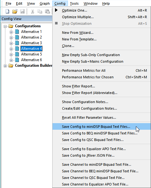
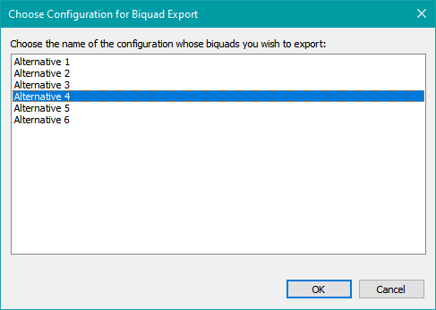
If the project contains more than one configuration, you'll need to select which configuration whose filters you wish to export. This selection is made in the Choose Configuration for Biquad Export dialog shown below. If the project contains only one configuration, this dialog will be skipped.
Once you've chosen the configuration, you'll be presented with the folder picker dialog shown below.
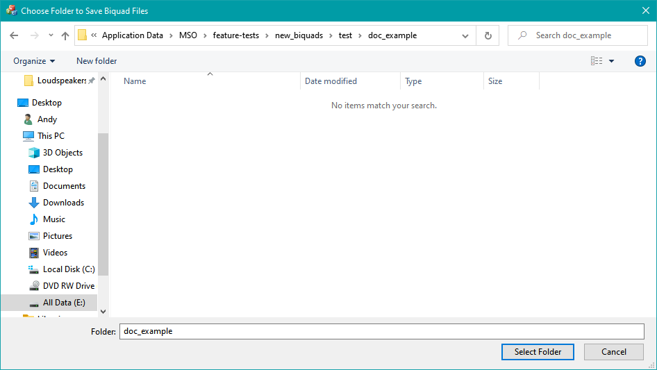
To avoid confusion or errors, it's best to either choose an existing directory that's empty or create a new, empty directory. After choosing Select Folder, all biquads for all channels of the chosen configuration will be saved to the folder you choose. The names of the exported files will be the same as the MSO channel names. If the MSO channel name has a character that's illegal for a file name (such as the ":" character), it will be replaced by a legal character.
Exporting Biquad Text of All Channels Using the Config View Context Menu
As an alternative to using the main menu, you can export the biquad files for all channels of a configuration by using the context menu that's shown when you right-click on the configuration's folder icon or name in the Config View as shown below.
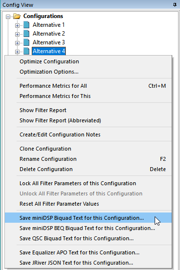
For miniDSP devices, choose Save miniDSP Biquad Text for this Configuration. For QSC devices, choose Save QSC Biquad Text for this Configuration. When you choose one of these commands, you'll be taken directly to the folder picker dialog shown above, for which the instructions above apply.
Exporting Biquad Text of a Single Channel of a Configuration
When exporting biquad text, the recommended method is to do so for all channels of a configuration at once using the methods in the sections above. Using those methods will require the least amount of effort on your part. Should you need to export the biquad information of a single filter channel at a time, that can be done through either the Config View or the main menu as described below.
Exporting Biquad Text of a Single Channel Using the Config View
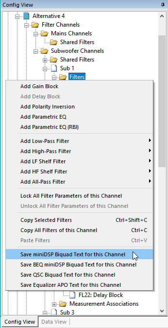
The first method of exporting the biquad information of a single filter channel is to use the Config View. In the Config View, navigate to the filter channel whose biquads you wish to export, then select the Filters folder node of this channel. For miniDSP devices, right-click this node and choose Save miniDSP Biquad Text for this Channel. For QSC devices, right-click this node and choose Save QSC Biquad Text for this Channel. This method is shown below.
Exporting Biquad Text of a Single Channel Using the Main Menu
The second method of exporting the biquad information of a single filter channel uses the main menu. For miniDSP devices, choose Config, Save Channel to miniDSP Biquad Text File from the main menu. For QSC devices, choose Config, Save Channel to QSC Biquad Text File. Either command will bring up the dialog shown below.
The Channels for Biquad File Save Dialog
The Channels for Biquad File Save dialog allows you to select a combination of configuration and channel for the biquads you wish to save to a file. It is shown below.
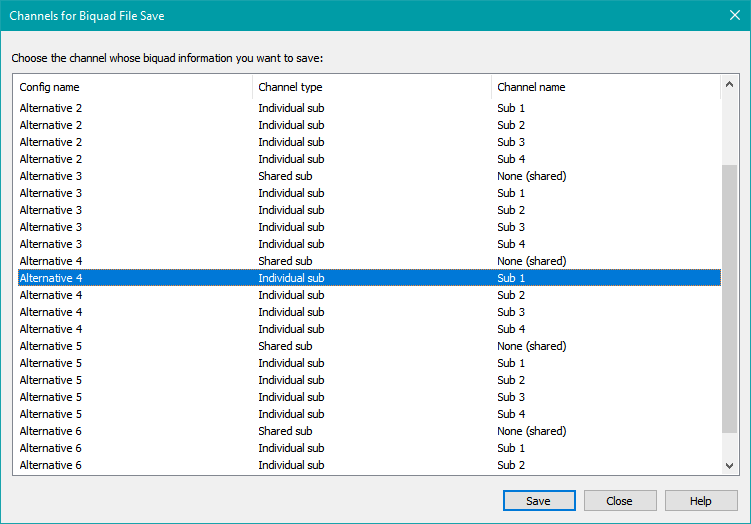
Navigate to the row that contains the combination of configuration name and channel name for the channel whose biquads you wish to export. Press the Save button. You'll be presented with a standard Windows File, Save dialog. Choose the desired folder and file name for the saved file, then click Save in that dialog. You can select another configuration/channel combination in the Channels for Biquad File Save dialog, then repeat the procedure to save each file. Do this as many times as you need to for the configuration, then press Close to close the Channels for Biquad File Save dialog.
Extending Filter Capacity by Using Crossover Biquads
On the Biquad Properties property page of the Application Options property sheet, the checkbox labeled Use miniDSP crossover biquads if output biquad limit exceeded enables the MSO feature to extend the number of available biquads. Saving biquad files when using this feature is done exactly the same way as conventionally saving biquad files. However, if the number of biquads needed for a given MSO filter export exceeds the normal miniDSP biquad capacity, additional biquad files will be saved. The additional files are for entry into the crossover biquads. These will be automatically generated and will have the same name as that used for the corresponding output biquad file, but with "_xo" appended to it before the extension. For instance, if the biquad count exceeds the biquad capacity and the normal save operation would result in an output biquad file named "chan1.txt", an additional file, named "chan1_xo.txt" will be automatically generated and will contain the biquads to be pasted into the crossover in the "Crossover advanced mode" of the miniDSP software.
MSO attempts to fill up the crossover biquads first, then uses the output biquads for the rest (if any). The reason for this behavior is that some of MSO's filter types require as many as four biquads to implement. It's possible that such a filter could be split up between the crossover and output biquads. If the output biquads were populated first, such a filter would be partly implemented on the output side of the output biquads and the input side of the crossover biquads. But the ordering of biquads within these more complex filters is optimized to prevent internal digital clipping in fixed-point DSPs. Splitting up a filter in this way would alter the biquad order within such filters, among other problems. By filling up the crossover biquads first, any filter that uses more than one biquad and that gets split between crossover and output biquads has some of its biquads at the output side of the crossover and the rest at the input side of the output biquads. This preserves the biquad order within these multi-biquad filters and also keeps the individual biquads of such filters contiguous in a signal-processing sense.
This property of filling up the crossover biquads first can cause unusual results in certain specific situations. Suppose you're using a miniDSP device with an output capacity of six biquads and a crossover capacity of eight biquads, and have a channel configuration in MSO with seven PEQs. These seven PEQs will require seven biquads. In this case, MSO will put all seven of them in the crossover biquads, padding the crossover to eight as required for the copy/paste in the miniDSP "Crossover advanced mode". When saving the biquad files and choosing, say, "chan1.txt" for the output biquad file name, two biquad files will be created: "chan1.txt" and "chan1_xo.txt". The "chan1_xo.txt" will contain all the data needed for implementing the seven biquads in the crossover, and the "chan1.txt" will not contain any biquad data at all, only a note saying that all the needed data are in "chan1_xo.txt". When saving only a single output channel's biquads, the file name you choose in the resulting file save dialog should always be the name of the output biquad file. The name and content of the crossover biquad file will be automatically generated if needed.
The Equivalence of Input Filters and Replicated Output Filters
A useful filter equivalence relationship exists involving input filters and replicated output filters. Suppose you have an MSO shared sub channel with filters FL1, FL2, FL3 and FL4. An exact equivalent circuit can be made by removing these filters from the shared (input) channel and replicating all of them in all of the miniDSP output channels. Although somewhat wasteful of filters, one can make use of the biquads contained in the seldom-used miniDSP crossover filters to implement them. By using the Use miniDSP crossover biquads if output biquad limit exceeded option on the Biquad Properties property page, the MSO biquad export will automatically do this filter equivalence transformation for you when needed. It will then automatically create the biquad text files to implement the extra filters using the crossover biquads if necessary.
The MSO Shared Biquad Count Can Be Greater Than the miniDSP Input Biquad Capacity
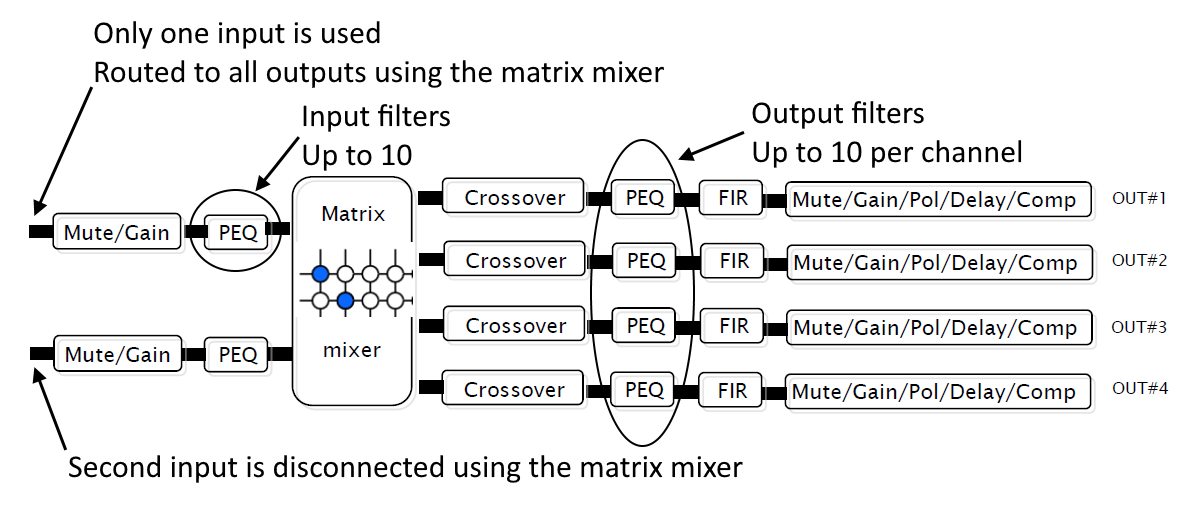
When not using BEQ (described below), a new feature of MSO v2 makes it possible to have more shared PEQs in a configuration than the input biquad capacity of the miniDSP hardware. This is made possible by the filter equivalence relationship described above. For instance, a miniDSP 2x4 HD has the following biquads available.
10 input biquads
8 crossover biquads
10 output biquads
This means that in passing from input to output, the signal goes through 28 biquads: first the 10 input biquads, then the 8 crossover biquads, then finally 10 output biquads. See the block diagram below.
One result that's not immediately obvious is that the filter equivalence relationship described above allows an MSO configuration to have, for instance:
14 shared sub PEQs and
14 per-sub PEQs.
This would be accomplished as follows:
10 of the 14 shared sub PEQs implemented using 10 input biquads
The remaining 4 shared sub PEQs implemented using 4 biquads, each replicated into the crossover of each output channel
4 of the 14 per-sub PEQs implemented in the crossover
The remaining 10 of the 14 per-sub PEQs implemented using the 10 output biquads
As long as the number of shared PEQs plus output PEQs in MSO is not greater than 28, MSO will figure out the biquad allocation automatically when exporting. The only requirement is that you save the biquads for all channels of the configuration as described above. It doesn't work when saving a single channel at a time. This is not really a problem, as saving all the biquads for all channels of the configuration is the preferred way to export biquads, as it requires much less effort than saving individual channels.
Using BEQ Biquad Export Support
BEQ is a collection of programs and a database used to equalize the bass of individual movies to counteract bass roll-off that may have been imposed in their production process.
The BEQ implementation makes use of the input filters of miniDSP devices. In MSO, it's also common to use shared sub filters. These are also implemented using the miniDSP input filters. Attempting to use such shared sub filters in MSO, together with BEQ, would create a conflict wherein both systems are trying to use the miniDSP input filters at once. MSO resolves this conflict by using a special set of biquad export commands designed for use with BEQ. These commands are described below.
These commands work by making use of the filter equivalence relationship discussed above. When using the Use miniDSP crossover biquads if output biquad limit exceeded option in the Application Options property sheet, together with one of the BEQ biquad export commands, the number of per-sub PEQs plus the number of shared PEQs that you use in MSO can be as high as eighteen for the miniDSP 2x4 HD, while still freeing up all ten input PEQ slots for BEQ to use.
This technique also completely eliminates the need for any biquad merging that may be provided by some of the BEQ software, as MSO won't use any input biquads for this case at all. In other words, all shared filters that would ordinarily end up in the miniDSP input biquads are removed, then replicated in each output channel, using the crossover biquads as needed. The price paid for this feature is the need to copy and paste the crossover biquad file contents (if any) into the miniDSP crossover instead of using the more convenient file import for the output biquads.
Exporting BEQ Biquad Text of All Channels of a Configuration
The simplest way to export biquads for use with BEQ in the miniDSP is to do so for all channels at once. There are two ways to do this.
- Use the main menu option to save the BEQ biquads for all channels.
- Use the context menu in the Config View to save the BEQ biquads for all channels.
These options are summarized below.
Exporting BEQ Biquad Text of All Channels Using the Main Menu
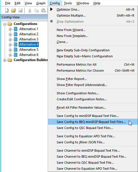
From the main menu, choose Config, Save Config to BEQ miniDSP Biquad Text Files as shown below.
If the project contains more than one configuration, you'll select which configuration whose filters you wish to export using the Choose Configuration for Biquad Export dialog shown above. If the project contains only one configuration, this dialog will be skipped.
Once you've chosen the configuration and pressed OK, you'll be presented with the previously described folder picker dialog. When using this dialog, it's best to either choose an existing empty directory or create a new empty directory. After choosing Select Folder, all biquads for all channels of the chosen configuration will be saved to the folder you choose. The names of the exported files will be the same as the MSO channel names. If the MSO channel name has a character that's illegal for a file name (such as the ":" character), it will be replaced by a legal character.
Exporting BEQ Biquad Text of All Channels Using the Config View Context Menu
You can also export the BEQ biquad files for all channels of a configuration by using the context menu that's shown when you right-click on the configuration's folder icon or name in the Config View as shown below.
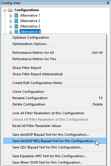
When you run this command, you'll be taken directly to the folder picker dialog shown above, for which the same instructions apply.
Exporting BEQ Biquad Text of a Single Channel of a Configuration
When you export BEQ biquad text, the recommended way is to export the data for all channels of a configuration at once using the methods already described. Using those methods will require the least amount of effort on your part. Should you need to export the BEQ biquad information of a single filter channel at a time, that can be done using one of the two techniques described below.
- Use the context menu in the Config View to select a configuration and channel for the BEQ biquads you wish to save.
- Use the main menu option to open a dialog box that allows you to choose the configuration and channel for the BEQ biquads you wish to save.
These options are discussed next.
Exporting BEQ Biquad Text of a Single Channel Using the Config View
The first method of exporting single-channel BEQ biquad information is to use the Config View. In the Config View, navigate to the filter channel whose biquads you wish to export, then select the Filters folder node of this channel. Right-click this node and choose Save BEQ miniDSP Biquad Text for this Channel from the context menu. This method is shown below.
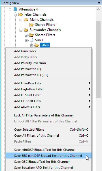
Exporting BEQ Biquad Text of a Single Channel Using the Main Menu
The second method of exporting single-channel BEQ biquad information uses the main menu. From the main menu, choose Config, Save Channel to BEQ miniDSP Biquad Text File. This command will bring up the dialog shown below.
The Channels for BEQ miniDSP Biquad File Save Dialog
The Channels for BEQ miniDSP Biquad File Save dialog allows you to select a combination of configuration and channel for the biquads you wish to save to a file. It is shown below.
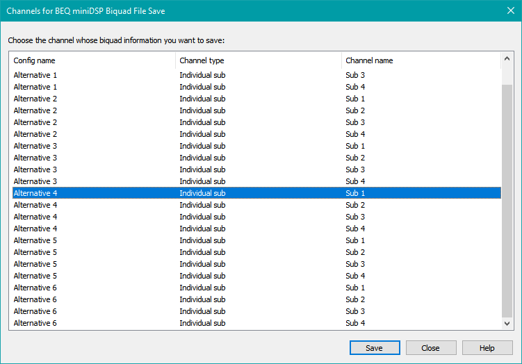
This dialog differs slightly from the non-BEQ version discussed above. The difference is that the BEQ version will never show shared channels, as BEQ export does not use them. It will use the crossover biquads if that option has been enabled on the Biquad Properties property page.
To export the desired channel's biquads, navigate to the row that contains the combination of configuration name and channel name for the channel whose biquads you wish to export. Press the Save button. You'll be presented with a standard Windows File, Save dialog. Choose the desired folder and file name for the saved file, then click Save in that dialog. You can select another configuration/channel combination in the Channels for BEQ miniDSP Biquad File Save dialog, then repeat the procedure to save each file. Do this as many times as you need to for the configuration, then press Close to close the dialog.
After Exporting Biquad Information
Once the biquad text files have been exported, you can use each text file to import an entire channel's biquads into the miniDSP. The miniDSP plugin software will configure all the filter parameters of all the filters in that channel at once.
Importing the Biquad Text Into the miniDSP 2x4 HD
For importing the MSO-generated biquad files into the miniDSP device using the Device Console software, see the miniDSP documentation for Parametric EQ and for Crossover.
Importing the Biquad Text Into QSC Devices
See the QSC IIR Custom Filter Component documentation for instructions for importing the biquad files created by MSO.
Setting the Delay and Gain Values
For information about determining the delay and gain values to use after an optimization, see the filter report section above. For information about entering these values into the miniDSP device, see their Device Console documentation for setting delays.
Saving Configurations in Equalizer APO Format
This feature is only for two-channel systems using a Windows-based HTPC with multiple subwoofers. The custom signal routing feature of the Equalizer APO software can be used to implement the required bass management. It is the subject of a dedicated article.