Preparing for an Optimization
Specifying Optimization Options
Before running an automated optimization, the optimization options must be set. If you run the Configuration Wizard to create a configuration, and chose the Launch Optimization Options dialog when done option on the last page of the wizard, the Optimization Options property sheet will be automatically launched when you're done with the wizard. You can also launch this property sheet at any time using various menu choices.
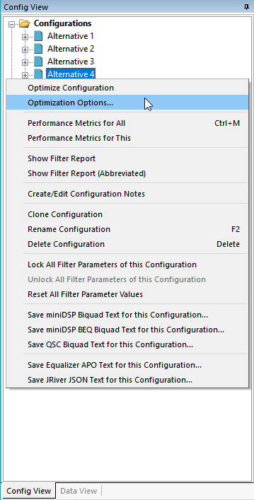
One way is use the Config View to select the icon at the root of the configuration whose optimization options you wish to set, then right-click and choose Optimization Options... as shown below.
Another way is to use the main menu. Choose Tools, Optimization Options. This will bring up a configuration picker dialog as shown below.
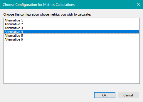
After selecting the configuration you want, you can either double-click it, press Enter or press the OK button to finalize your choice.
Either of these two methods will bring up the property sheet shown below.
The individual property pages of this property sheet are described below.
The Optimization Type Property Page
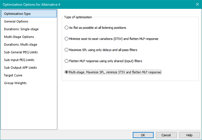
The Optimization Type property page of the Optimization Options dialog is shown below.
One important side effect of choosing the optimization type on this page is its effect on the enabling and disabling of controls on subsequent pages. For instance, if you choose the multi-stage optimization type on this page, all the controls on the Durations: Single-stage property page will be disabled, as those controls aren't pertinent to multi-stage optimization. This simplifies data entry by excluding irrelevant choices.
The optimization types you can use are described below.
As flat as possible at all listening positions
Using this method, MSO tries to get the frequency response at each listening position to match the target curve (which is flat by default) as closely as possible. It uses the following optimization procedure.
- For each listening position, a single error is computed for the RMS deviation over frequency from flat response (or the target curve if specified).
- The errors at each position are combined using an RMS calculation to get a single composite error. This combined error may be weighted according to position if the weighting option is chosen on the Group Weights property page.
- The optimizer minimizes this composite error.
Using this method, the seat-to-seat variation is not explicitly calculated, but is implicitly improved by the improved response flatness at all positions.
Minimize seat-to-seat variations (STSV) and flatten MLP response
When you choose this optimization option, MSO performs the following calculations when optimizing.
- At the main listening position, a single error is computed for the RMS deviation over frequency from flat response (or the target curve if specified).
- The average curve over all listening positions is computed.
- For each listening position, a single error is computed for the RMS deviation over frequency from the average curve.
- The errors at each position are combined using an RMS calculation to get a single composite error for the seat-to-seat variation (STSV). This combined error may be weighted according to position if the weighting option is chosen on the Group Weights property page.
- The flatness error at the MLP is combined with the STSV using a weighted RMS computation described in the How Optimization Errors are Calculated: the Details topic in the Tech Topics section.
- The optimizer minimizes this composite error.
Maximize SPL using only delays and all-pass filters
Optimizing using this option causes MSO to perform the following procedure.
- All unlocked PEQs are forced to the flat-response state.
- The lock states of all parameters of all filters are saved.
- All parameters of all filters except output-channel all-pass filters and delays are locked.
- The parameters of the output-channel all-pass filters and delays are adjusted to minimize SPL penalty by trying to get all the subs to be acoustically in phase with one another at all listening positions and frequencies.
- If the weighting option is chosen on the Group Weights property page, listening positions with higher weights will count more toward the SPL penalty than positions with lower ones.
- The saved lock states of all filters are restored, unlocking filter parameters that were temporarily locked at the beginning of optimization.
The details of the SPL penalty calculation will be provided in the How Optimization Errors are Calculated: the Details page as time permits.
This option is only available for sub-only configurations.
Flatten MLP response using only shared (input) filters
When you choose this option for optimization, the following procedure is performed.
- All unlocked input filters are forced to their default state. This means input PEQs are reset to force them to have a flat response.
- The lock states of all parameters of all filters are saved.
- All parameters of all output-channel filters are locked.
- The optimizer adjusts the parameters of the input filters so that the MLP RMS deviation over frequency from flat response (or the target curve if specified) is minimized.
- The saved lock states of all filters are restored, unlocking filter parameters that were temporarily locked at the beginning of optimization.
This option is only available for configurations with at least 4 shared PEQ filters. When you run this procedure on a sub-only configuration, it does not affect the SPL penalty or STSV.
Multi-stage: Maximize SPL, minimize STSV and flatten MLP response
When you choose this optimization option, three optimizations are performed in sequence.
-
First, the equivalent of the Maximize SPL using only delays and all-pass filters optimization type is performed.
- Upon completion, the SPL penalty obtained by this optimization is passed on to the next optimization stage.
-
Next, a modified version of the Minimize seat-to-seat variations (STSV) and flatten MLP response optimization is run.
- In addition to the STSV and MLP flatness calculation, the SPL penalty is computed.
- The SPL penalty is used as a constraint on the solution.
- The value of the SPL penalty passed on from the previous optimization stage is added to the allowable increase entered on the General Options property page. This becomes the maximum allowable SPL penalty at this stage.
- The STSV and MLP flatness errors are minimized, subject to the SPL penalty constraint.
-
Finally, the equivalent of the Flatten MLP response using only shared (input) filters is run.
- This resets all the input PEQs to their flat response state, so the system frequency response will at first appear somewhat degraded until the input PEQ adjustment process is completed.
- This process of flattening the MLP does not affect either the SPL penalty or the STSV.
This option is only available for sub-only configurations with at least 4 shared PEQ filters.
The General Options Property Page
The General Options property page is shown below.
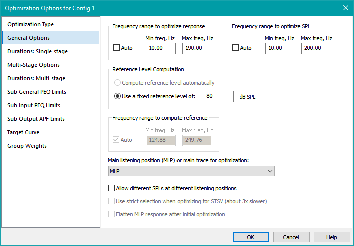
This property page gathers important options that pertain to all optimization types. Its controls are as described below.
The Frequency range to optimize response Controls
For this frequency range, "response" refers to several categories of optimization data.
- The flatness measure at any position including the MLP
- The seat-to-seat variation (STSV)
The associated responses are calculated for all optimization types except Maximize SPL using only delays and all-pass filters.
The Auto checkbox has the following effect.
- When Auto is checked, the frequency range is the same as that of the data, but with a maximum allowable upper frequency limit applied.
- When Auto is unchecked, the minimum and maximum optimization frequencies become what you choose, provided their values are within the range of the data and the maximum frequency is not above the allowed upper frequency limit.
The Frequency range to optimize SPL Controls
These controls apply only to the following optimization types.
- Maximize SPL using only delays and all-pass filters
- Multi-stage: Maximize SPL, minimize STSV and flatten MLP response
For all other optimization types, these controls are disabled.
The Auto checkbox has the following effect.
- When Auto is checked, the minimum and maximum optimization frequencies are the same as the Frequency range to optimize response control values.
- When Auto is unchecked, the minimum and maximum optimization frequencies become what you choose, provided their values are within the range of the data and the maximum frequency is not above the allowed upper frequency limit.
Making the Frequency range to optimize SPL wider than the Frequency range to optimize response can be beneficial. Having the subs be acoustically in phase with one another at the very lowest and very highest frequencies can maximize output and prevent response irregularities respectively.
The Reference Level Computation Controls
The Reference Level Computation controls are described below. Please note that the reference level in MSO has nothing whatsoever to do with AVR reference levels.
Compute reference level automatically
For configurations with subs and mains, Compute reference level automatically is the default option for setting the reference level. When this option is chosen, the average response of subs and mains combined, over the frequency range specified in Frequency range to compute reference, (see below) is used as the reference level. Choose this frequency range to be the upper end of the optimization frequency range so MSO will adjust the sub levels to match the mains.
Use a fixed reference level
When using a sub-only configuration, you are restricted to using this option. See Reference level below for more information.
You can also specify this option for subs+mains configurations. You might want to do this if your main speakers do not have baffle step compensation and your DSP gives you the ability to equalize them. Using an LF shelving filter with boost, along with a fixed reference level, could accomplish a DIY baffle step compensation for your main speakers.
Reference level
If you've chosen Use a fixed reference level per the above, you'll need to set that level (in dB SPL) here. This is required for sub-only configurations. When using a target curve that isn't flat, the reference level is the response level at the highest response optimization frequency (from the Frequency range to optimize response controls).
The Reference Level Controls May be Disabled
When you choose the Maximize SPL using only delays and all-pass filters optimization type on the Optimization Type property page, all reference level controls on this property page are disabled. That optimization type does not use a reference level.
The Frequency range to compute reference Controls
When specifying optimization options for a "Subs+Mains" configuration, it becomes possible to select the Compute reference level automatically option described above. When this is done, the Frequency range to compute reference controls will be enabled. In this mode, the reference level is not specified directly as a numeric value, but indirectly using the range of frequencies specified in these controls. The average value of the combined response of mains and subs at a given listening position is computed over the frequency range specified in the Frequency range to compute reference fields. This average value becomes the reference level for that listening position.
This "self-seeking" reference level is made possible by MSO's restriction of not allowing gain blocks in mains channels. The Frequency range to compute reference should be at the high end of the frequency range where the response of the mains (whose gain is fixed) dominates. This technique ensures that MSO can adjust the level of the subs to match the level of the mains, just as you would if you were performing a sub trim manually by using the RTA mode of REW. Using such a manual procedure, you might adjust the sub trim while observing the combined response of subs and main speakers. MSO tries to emulate this approach by figuring out the reference level at the high end of the frequency band automatically, then adjusting the sub levels to match this computed reference level.
Main listening position (MLP) or main trace for optimization
Beginning in MSO 1.1.1, you must always choose which listening position or trace is the MLP or "main trace". Choose the appropriate position from the combo box. If you have a measurement group that is named "MLP", it will be chosen automatically for you.
Other Option Checkboxes
Allow different SPLs at different listening positions
- This option should almost always be unchecked. When unchecked, MSO tries to force the response curves at each listening position to lie right on top of one another, with no average level shifts between them.
- When checked, MSO allows the different listening positions to have different average SPLs over frequency. This should only be used in rare circumstances. One such circumstance might be having subs only in the front of the room, and optimizing responses over multiple rows of seats. With this option checked, MSO would allow the rear rows of seats to have a lower average SPL over frequency than the front ones.
Use strict selection when optimizing for STSV
This option should almost always be unchecked. When checked, it enables an optimization technique called multi-objective optimization, which uses a much more strict algorithm for selecting potential solutions. It is around three times slower than the normal algorithm, but can, under certain circumstances, arrive at solutions that the normal algorithm might miss.
Flatten MLP response after initial optimization
When using any of the optimization types listed below,
- As flat as possible at all listening positions
- Minimize seat-to-seat variations (STSV) and flatten MLP response
- Maximize SPL using only delays and all-pass filters
you can check the Flatten MLP response after initial optimization checkbox. When checked, it turns a single-stage optimization into a two-stage one. At the second optimization stage, the equivalent of a Flatten MLP response using only shared (input) filters optimization will be run.
For the first two optimization types, performing a separate step to flatten the MLP response will often give better results at the MLP than an approach taking all listening positions into account.
For the third optimization type above, it allows you to get the highest possible SPL, along with the flattest MLP response possible, in one optimization run. This approach neglects seat-to-seat variation, so the results may only be useful for reference purposes.
The Durations: Single-stage Property Page
The Durations: Single-stage property page is shown below.
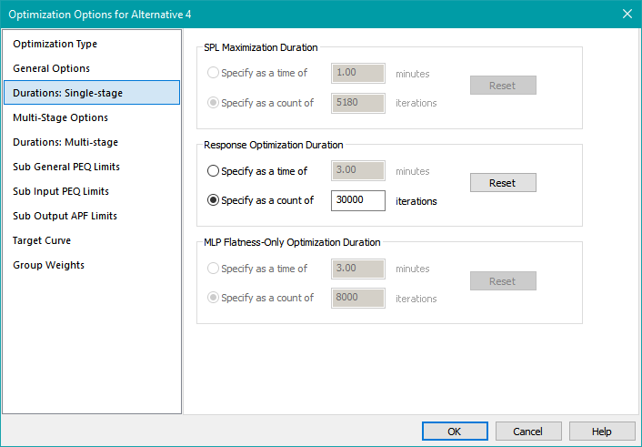
The Controls of the Duration Control Groups
All three duration control groups have the same controls with the same functionality, so they'll be discussed as one.
Each duration control group contains the following controls.
- A pair of radio buttons that allow you to choose between specifying the optimization time in minutes or as a count of iterations.
- Each radio button has a corresponding edit control for specifying time in minutes or an iteration count.
- A Reset button that loads the chosen edit control with the default value for either the optimization time in minutes or the iteration count.
The behavior of the Reset button is as follows.
-
When the selected radio button specifies an optimization time in minutes, only its corresponding edit control gets the default value. This default value has the following properties.
- It depends on the number of concurrent threads supported by the processor.
- It doesn't take into account processor speed or the complexity of the configuration.
-
When the selected radio button specifies an optimization duration as an iteration count, only its corresponding edit control gets the default value. This default value has the following characteristics.
- It has no dependency on the number of concurrent threads supported by the processor.
- It has no dependency on the processor speed.
- It doesn't take into account the complexity of the configuration.
Best practice in MSO is to use an iteration count rather than a time. This will give similar results across machines of widely varying capabilities. Forum troubleshooting is also made easier, as the number of confounding factors when examining results is reduced.
Enabling of Duration Control Groups
The three control groups on this page allow you to specify separate optimization durations for different optimization types. These options only apply to the first five optimization types on the Optimization Type property page. These are the single-stage optimization types. If you need to specify optimization durations for the Multi-stage: Maximize SPL, minimize STSV and flatten response type optimization type, you'll need to use the Durations: Multi-stage property page.
Enabling of the SPL Maximization Duration, Response Optimization Duration and MLP Flatness-Only Optimization Duration control groups is as follows.
- If the Multi-stage: Maximize SPL, minimize STSV and flatten response type optimization type is chosen on the Optimization Type property page, all the controls on this page are disabled, and you must use the Durations: Multi-stage property page to specify optimization durations.
- If the Maximize SPL using only delays and all-pass filters optimization type is chosen, the controls in the SPL Maximization Duration control group will be enabled.
-
If either of the two optimization types listed below is chosen, the Response Optimization Duration control group will be enabled.
- As flat as possible at all listening positions
- Minimize seat-to-seat variations (STSV) and flatten MLP response
-
The MLP Flatness-Only Optimization Duration control group will be enabled under either of the following conditions.
- The Flatten MLP response using only shared (input) filters optimization type has been selected.
- The Flatten MLP response after initial optimization checkbox on the General Options property page is enabled and checked.
The Multi-Stage Options Property Page
The Multi-Stage Options property page is shown below.
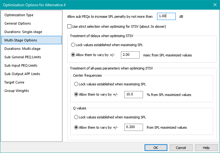
These options all pertain only to the second optimization stage of the Multi-stage: Maximize SPL, minimize STSV and flatten MLP response optimization type chosen on the Optimization Type property page. At this point of the multi-stage optimization, the SPL has already been maximized at the first stage using only delays and all-pass filters, and with all PEQs set to a flat response and locked. The SPL penalty value obtained in the first stage has been passed on to the second stage to be used as a constraint when minimizing seat-to-seat variation (STSV). That's where these options come in.
Constraining the Worst-Case SPL Penalty
Suppose that the SPL maximization of the first optimization stage results in an SPL penalty of, say, 1.8 dB. This value is passed on to the second optimization stage, where the offset value specified in the Allow sub PEQs to increase SPL penalty by not more than edit control of this property page shown above is added to it. In the case illustrated in the image above, this offset is 1.0 dB, so the SPL penalty when minimizing the STSV in the second optimization stage is constrained to be not more than 2.8 dB.
By specifying different values of this offset, you can obtain different compromises between SPL penalty and STSV, as illustrated in detail in the earlier multiple-configuration optimization example.
Use strict selection when optimizing for STSV
This option should almost always be unchecked. When checked, it enables an optimization technique called multi-objective optimization, which uses a much more strict algorithm for selecting potential solutions. It is around three times slower than the normal algorithm, but can, under certain circumstances, arrive at solutions that the normal algorithm might miss.
Treatment of Delays and All-Pass Parameters When Optimizing STSV
After the first-stage optimization of SPL completes but before the STSV optimization, the parameter value limits of delays and all-pass parameters are adjusted according to criteria specified here. This is to help improve convergence of the STSV optimization. The delay values of delay blocks, along with the Q and center frequency of all-pass filters found in the first optimization stage are used as the centers of their respective allowable parameter ranges.
In the most restrictive case, these parameters can be locked at the values found at the first optimization stage. This is accomplished using the Lock values established when maximizing SPL radio button in each of the three control groups shown above.
To allow more flexibility (and potentially better results), use the Allow them to vary by radio buttons. These tolerances are expressed in different ways for the different parameter types.
- For delay parameter limits, a tolerance of milliseconds is used.
- For all-pass center frequency parameter limits, a percentage tolerance is used.
- For all-pass Q parameter limits, a unitless value tolerance is used.
Limits that you've placed elsewhere on these parameter values will still be respected, so the actual limits may end up being narrower than they might first appear from an estimate using the values specified on this property page.
The Durations: Multi-stage Property Page
The Durations: Multi-stage property page is shown below.
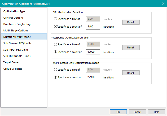
The Control Groups for Duration
The optimization durations you specify on this property page pertain only to the Multi-stage: Maximize SPL, minimize STSV and flatten MLP response optimization type chosen on the Optimization Type property page. The three stages of the optimization were described earlier. Since each stage requires a different amount of processing, the durations of each stage must be specified individually.
All three control groups are always enabled, as all three stages of this optimization type are always performed. The usage of each control group is described below.
The Controls of the Duration Control Groups
All three duration control groups have the same controls with the same functionality, so they'll be discussed as one.
Each duration control group contains the following controls.
- A pair of radio buttons that allow you to choose between specifying the optimization time in minutes or as a count of iterations.
- Each radio button has a corresponding edit control for specifying time in minutes or an iteration count.
- A Reset button that loads the chosen edit control with the default value for either the optimization time in minutes or the iteration count.
The behavior of the Reset button is as follows.
-
When the selected radio button specifies an optimization time in minutes, only its corresponding edit control gets the default value. This default value has the following properties.
- It depends on the number of concurrent threads supported by the processor.
- It doesn't take into account processor speed or the complexity of the configuration.
-
When the selected radio button specifies an optimization duration as an iteration count, only its corresponding edit control gets the default value. This default value has the following characteristics.
- It has no dependency on the number of concurrent threads supported by the processor.
- It has no dependency on the processor speed.
- It doesn't take into account the complexity of the configuration.
Best practice in MSO is to use an iteration count rather than a time. This will give similar results across machines of widely varying capabilities. Forum troubleshooting is also made easier, as the number of confounding factors when examining results is reduced.
The Property Pages for Setting Filter Parameter Limits
MSO allows you to specify PEQ parameter limits and allowed overall PEQ boost/cut limits using two different methods.
- You can set the PEQ parameter value limits and overall boost/cut limits of all sub PEQs at once.
- You can also specify the PEQ parameter value limits and overall boost/cut limits of input (shared) and output (per-sub) PEQs separately.
The same options are available for main speaker PEQs when subs+mains configurations are used.
Overview: The General and Input PEQ Limits Property Pages
An example of one of the PEQ Limits property pages is shown below.
Reference documentation for these property pages is presented in the next section. This overview section provides a brief summary of the purpose of these pages.
The General PEQ Limits property page has two modes, set by radio buttons that allow you the following choices:
- Choosing Use this page to set only output PEQ parameter limits configures the page so that the limits you set apply only to PEQs in the output channel of your DSP device.
- Choosing Use this page to set all PEQ parameter limits configures the page so that the limits you set apply to PEQs in both the input and output channels of your DSP device.
The Input PEQ Limits property page also has radio buttons that allow a similar option choice. These radio buttons are linked to the ones on the General PEQ Limits property page, so that when you change their state on one page, the other page automatically changes to match it.
- Choosing Use this page to set only input PEQ parameter limits configures the page so that the limits you set apply only to PEQs in the input channel of your DSP device. When you choose this option, the Use this page to set only output PEQ parameter limits option on the General PEQ Limits property page will be automatically chosen (and vice versa).
- Choosing Do not use this page to set any PEQ parameter limits disables this page, while enabling the Use this page to set all PEQ parameter limits option of the General PEQ Limits property page. In this mode, the General PEQ Limits property page controls all individual PEQ and overall PEQ boost/cut limits.
How the PEQ Limit Controls are Populated
There's more to the behavior of the PEQ limit controls than first meets the eye. When any Keep existing limit checkbox is checked, its corresponding edit control shows the condition of the filters themselves for that parameter limit. If all filters have the same limit value for a parameter, you'll see a single number in the edit control. If there's a mixture of parameter limit values, you might see something like what's in the image above.
When you uncheck a Keep existing limit checkbox, the control content just shows what you enter, which will end in the PEQs if you close the property sheet using the OK button.
An Important Note on PEQ Center Frequency Range
On these PEQ parameter limit property pages, it's possible to choose a PEQ center frequency range that exceeds the optimization frequency range specified on the General Options property page. Care should be taken when doing this, as it can lead to unexpected results. If this condition exists when an optimization is run, MSO will issue a warning by default before the optimization is allowed to continue. You can disable this warning on the UI Options page of the Application Options property sheet.
MSO uses separate frequency ranges for normal optimization and when computing the maximum total PEQ boost or cut. In the latter case, the frequency range used is chosen to include both the PEQ center frequency range you specify, as well as the optimization frequency range. This range is never narrower than the optimization frequency range, but it will be wider if the PEQ center frequency range is chosen to be wider than the optimization frequency range.
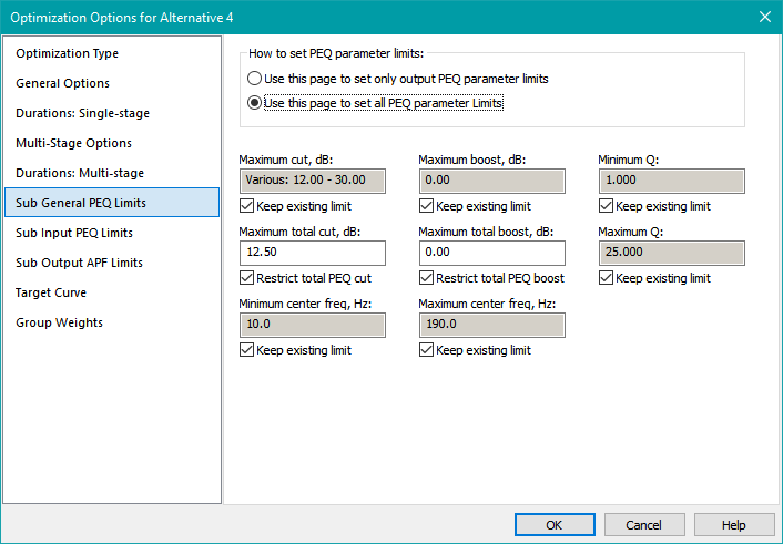
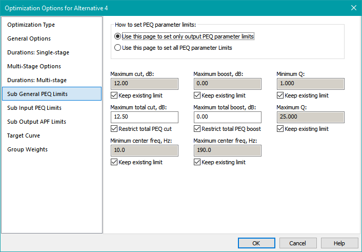
The Sub General PEQ Limits Property Page
The Sub General PEQ Limits property page is shown below. For information that's common to all PEQ limits property pages, see the topic The Property Pages for Setting Filter Parameter Limits.
The How to set PEQ parameter limits Radio Button Group
This radio button group has two options:
- Selecting the Use this page to set only output PEQ parameter limits option causes this property page to set parameter limits for only the PEQs in subwoofer output channels. The overall maximum PEQ boost and cut will only apply to the output channel portion of the subwoofer signal path.
- Selecting the Use this page to set all PEQ parameter limits option causes this property page to set parameter limits for PEQs in both input and output subwoofer channels. The overall maximum boost and cut will apply to the entire subwoofer signal path from input to output.
The Maximum cut, dB and Maximum boost, dB Fields
The values you enter into these fields go into the subwoofer PEQ filters themselves as gain limits. The PEQ maximum allowable gain in dB is set to the chosen value of Maximum boost, dB. The PEQ minimum allowable gain in dB is set to the negative of the chosen value of Maximum cut, dB. The subset of subwoofer PEQs into which these boost and cut limits are placed is determined by the state of the How to set PEQ parameter limits radio button group.
The Maximum total cut, dB and Maximum total boost, dB Fields
These values are used not for the subwoofer PEQs themselves, but as constraints for the optimizer so that it disallows the cumulative response of collections of PEQs in a given subwoofer channel from exceeding the specified maximum total boost or cut. This is to prevent undesired "stacking" of PEQs, where multiple individual PEQs line up at the same center frequency to provide a boost or cut much larger that that allowed for a single PEQ. The specified maximum total boost or cut must not be less than the corresponding maximum allowable boost or cut for individual subwoofer PEQs that you set in the PEQ limit value fields. These constraints may be applied either to the entire subwoofer path from DSP input to output, or only to the output path. The method of application is determined by the mode you select in the How to set PEQ parameter limits radio button group.
The Minimum center freq, Hz and Maximum center freq, Hz Fields
The minimum and maximum center frequency limit values are placed into the subwoofer PEQ filters themselves. Unless you have a compelling reason not to do so, these limits should be set to the same values as the minimum and maximum optimization frequency specified on the General Options property page. The subset of subwoofer PEQs into which these center frequency limits are placed is determined by the state of the How to set PEQ parameter limits radio button group.
The Minimum Q and Maximum Q Fields
The minimum and maximum Q limit values are entered into the subwoofer PEQ filters themselves. The subset of subwoofer PEQs into which these Q limits are placed is determined by the state of the How to set PEQ parameter limits radio button group. Some controversy exists around what these limits should be. Accepting the default limits set in Tools, Application Options, Filter Parameter Defaults, Parametric EQ is a reasonable rule of thumb for starting out.
The Sub Input PEQ Limits Property Page
The Sub Input PEQ Limits property page is shown below. For information that's common to all PEQ limits property pages, see the topic The Property Pages for Setting Filter Parameter Limits.
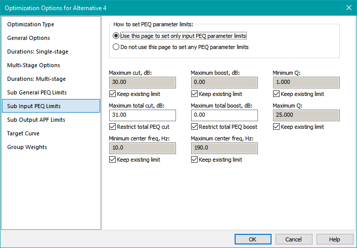
The How to set PEQ parameter limits Radio Button Group
This radio button group has two options:
- Selecting the Use this page to set only input PEQ parameter limits option causes this property page to set parameter limits for only the subwoofer PEQs in the input (shared) channel. The overall maximum subwoofer PEQ boost and cut will only apply to the input (shared) channel portion of the subwoofer signal path.
- Selecting the Do not use this page to set any PEQ parameter limits option causes this property page to become disabled. In this case, the corresponding radio button on the Sub General PEQ Limits property page will be automatically set to the Use this page to set all PEQ parameter limits state, enabling that page to control all subwoofer PEQ parameters and overall boost/cut limits for the subs.
All the subwoofer PEQ parameter value and overall boost/cut limit fields described below either apply only to the subwoofer input channel (if the Use this page to set only input PEQ parameter limits option is chosen), or are disabled (when the Do not use this page to set any PEQ parameter limits option is chosen).
The Maximum cut, dB and Maximum boost, dB Fields
The values you enter into these fields go into the subwoofer input PEQ filters themselves as gain limits. The PEQ maximum allowable gain in dB is set to the chosen value of Maximum boost, dB. The PEQ minimum allowable gain in dB is set to the negative of the chosen value of Maximum cut, dB.
The Maximum total cut, dB and Maximum total boost, dB Fields
These values are used not for the PEQs themselves, but as constraints for the optimizer so that it disallows the cumulative response of collections of PEQs in the subwoofer input channel from exceeding the specified maximum total boost or cut. This is to prevent undesired "stacking" of sub input PEQs, where multiple individual PEQs line up at the same center frequency to provide a boost or cut much larger that that allowed for a single PEQ. The specified maximum total boost or cut must not be less than the corresponding maximum allowable boost or cut for individual input channel PEQs that you set in the PEQ limit value fields.
The Minimum center freq, Hz and Maximum center freq, Hz Fields
The minimum and maximum center frequency limit values are placed into the subwoofer input PEQ filters. Unless you have a compelling reason not to do so, these limits should be set to the same values as the minimum and maximum optimization frequency specified on the General Options property page.
The Minimum Q and Maximum Q Fields
The minimum and maximum Q limit values are entered into the subwoofer input PEQ filters. Some controversy exists around what these limits should be. Accepting the default limits found in Tools, Application Options, Filter Parameter Defaults, Parametric EQ is a reasonable rule of thumb to start out.
The Sub Output APF Limits Property Page
The Sub Output APF Limits property page is shown below.
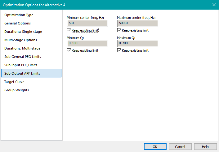
The Minimum center freq, Hz and Maximum center freq, Hz Fields
The minimum and maximum center frequency limit values are placed into the subwoofer output all-pass filters. You'll probably need to experiment with these limits based on SPL optimizations. The upper frequency limit should be well above the maximum optimization frequency.
The Minimum Q and Maximum Q Fields
The minimum and maximum Q limit values are entered into the subwoofer output all-pass filters. Experimentation has shown that a useful range is from about 0.1 to 0.7. Large Q limit values cause an undesirable rapid phase change with frequency.
Considerations When Optimizing Both Subs and Main Speakers
When you invoke the Optimization Options property sheet for a "subs+mains" configuration, you'll see two additional property pages listed. These are for specifying limits for main speaker PEQ parameters, as well as overall PEQ boost/cut limits for the main speaker signal paths. This situation is shown below.
The usage of the term "Shared PEQ Limits" for the main speaker channels is deliberate. For subs, "Input PEQ Limits" makes sense because there is a common, mono input channel in the subwoofer DSP device. But for main speakers, there is no such mono input source. However, MSO still uses the concept of a shared channel for main speakers. This is for filters that will be the same in all main channels. If you export e.g. biquad text files for the main channels of a subs+mains configuration, the shared main channel filters are replicated in all individual main channels.
Having shared filters in main channels is desirable to help prevent imaging problems that could occur with individual main channel EQ. MSO gives you the option of both, allowing you to make common adjustments to all main channels that might have fairly loose constraints, while having more restrictive constraints for individual main channel equalization to prevent possible imaging problems.
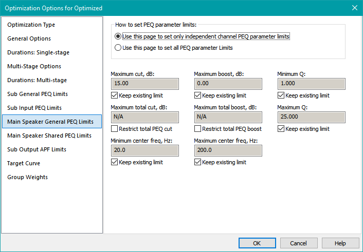
The Main Speaker General PEQ Limits Property Page
The Main Speaker General PEQ Limits property page is shown below.
The How to set PEQ parameter limits Radio Button Group
This radio button group has two options:
- Selecting the Use this page to set only independent channel PEQ parameter limits option causes this property page to set parameter limits for only the PEQs that are not shared among main speaker channels. The overall maximum PEQ boost and cut will only apply to the PEQs that are not shared among main channels.
- Selecting the Use this page to set all PEQ parameter limits option causes this property page to set parameter limits for both shared and independent main channel PEQs. The overall maximum boost and cut will apply to the entire main speaker signal path from input to output.
The Maximum cut, dB and Maximum boost, dB Fields
The values you enter into these fields go into the main speaker PEQ filters themselves as gain limits. The PEQ maximum allowable gain in dB is set to the chosen value of Maximum boost, dB. The PEQ minimum allowable gain in dB is set to the negative of the chosen value of Maximum cut, dB. The subset of main speaker PEQs into which these boost and cut limits are placed is determined by the state of the How to set PEQ parameter limits radio button group.
The Maximum total cut, dB and Maximum total boost, dB Fields
These values are used not for the main speaker PEQs themselves, but as constraints for the optimizer so that it disallows the cumulative response of collections of PEQs in a given main speaker channel from exceeding the specified maximum total boost or cut. This is to prevent undesired "stacking" of PEQs, where multiple individual PEQs line up at the same center frequency to provide a boost or cut much larger that that allowed for a single PEQ. The specified maximum total boost or cut must not be less than the corresponding maximum allowable boost or cut for individual main speaker PEQs that you set in the PEQ limit value fields. These constraints may be applied either to the entire main speaker path from DSP input to output, or only to the PEQs that aren't shared among main speaker channels. The method these limits are applied is determined by the mode you select in the How to set PEQ parameter limits radio button group.
The Minimum center freq, Hz and Maximum center freq, Hz Fields
The minimum and maximum center frequency limit values are placed into the main speaker PEQ filters themselves. The subset of main speaker PEQs into which these center frequency limits are placed is determined by the state of the How to set PEQ parameter limits radio button group.
The Minimum Q and Maximum Q Fields
The minimum and maximum Q limit values are entered into the main speaker PEQ filters themselves. The subset of main speaker PEQs into which these Q limits are placed is determined by the state of the How to set PEQ parameter limits radio button group. Some controversy exists around what these limits should be. Accepting the default limits set in Tools, Application Options, Filter Parameter Defaults, Parametric EQ is a reasonable rule of thumb for starting out.
The Main Speaker Shared PEQ Limits Property Page
The Main Speaker Shared PEQ Limits property page is shown below.
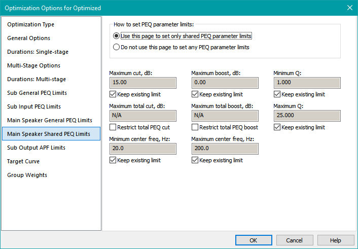
The How to set PEQ parameter limits Radio Button Group
This radio button group has two options:
- Selecting the Use this page to set only shared PEQ parameter limits option causes this property page to set parameter limits for only those PEQs that shared among main speaker channels. The overall maximum PEQ boost and cut will only apply to these shared main channel PEQs.
- Selecting the Do not use this page to set any PEQ parameter limits option causes this property page to become disabled. In this case, the corresponding radio button on the Main Speaker General PEQ Limits property page will be automatically set to the Use this page to set all PEQ parameter limits state, enabling that page to control all main speaker PEQ parameters and overall boost/cut limits for the main speakers.
All the main speaker PEQ parameter value and overall boost/cut limit fields described below either apply only to the shared main speakers (if the Use this page to set only shared PEQ parameter limits option is chosen), or are disabled (when the Do not use this page to set any PEQ parameter limits option is chosen).
The Maximum cut, dB and Maximum boost, dB Fields
The values you enter into these fields go into the main speaker shared PEQ filters themselves as gain limits. The PEQ maximum allowable gain in dB is set to the chosen value of Maximum boost, dB. The PEQ minimum allowable gain in dB is set to the negative of the chosen value of Maximum cut, dB.
The Maximum total cut, dB and Maximum total boost, dB Fields
These values are used not for the main speaker PEQs themselves, but as constraints for the optimizer so that it disallows the cumulative response of the shared main channel PEQs from exceeding the specified maximum total boost or cut. This is to prevent undesired "stacking" of PEQs, where multiple individual PEQs line up at the same center frequency to provide a boost or cut much larger that that allowed for a single PEQ. The specified maximum total boost or cut must not be less than the corresponding maximum allowable boost or cut for individual main speaker PEQs that you set in the PEQ limit value fields.
The Minimum center freq, Hz and Maximum center freq, Hz Fields
The minimum and maximum center frequency limit values are placed into the shared main speaker PEQ filters themselves.
The Minimum Q and Maximum Q Fields
The minimum and maximum Q limit values are entered into the shared main speaker PEQ filters themselves. Some controversy exists around what these limits should be. Accepting the default limits set in Tools, Application Options, Filter Parameter Defaults, Parametric EQ is a reasonable rule of thumb for starting out.
The Target Curve Property Page
A target curve (sometimes called a "house curve") can be imported in the Target Curve page. This property page is shown below.
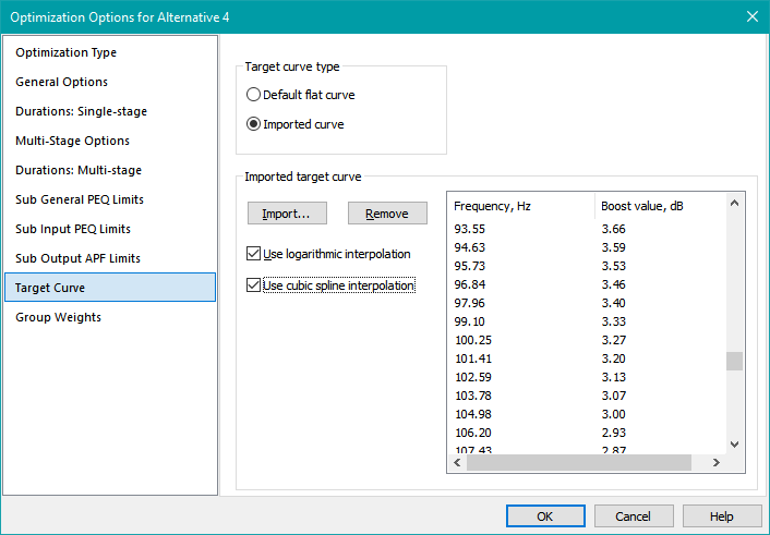
A target curve is a text file with two columns of data. The first column is the frequency in Hz, and the second column is the curve value in dB. You can also use text files having more than two columns of data, provided the first two columns are frequency in Hz and curve value in dB respectively. For files containing more than two columns of numbers, data after the second column is ignored. The data columns can be separated by spaces or tabs.
The Target curve type Control Group
You have two choices in the Target Curve Type control group.
- Choosing Default flat curve results in a target curve that's flat, with a level in dB SPL given by the reference level. When you choose this option, the controls in the Imported target curve control group below it will be disabled.
- When you choose the Imported curve option, the controls in the Imported target curve control group will be enabled, allowing you to import the curve and set its properties.
The Imported target curve Control Group
The Imported target curve control group contains the controls described below.
- The Import button launches a standard Windows file open dialog. If you import a file with the correct format, its contents will be shown in the two-column list on the right.
- The Remove button clears out any imported target curve shown in the two-column list.
- The Use logarithmic interpolation and Use cubic spline interpolation checkboxes are described in more detail below.
For complex curves, Use cubic spline interpolation is recommended as it will cause a smooth curve to be drawn between the target curve points.
It is recommended that the Use logarithmic interpolation option almost always be checked.
Creating Simple Target Curves
This section shows how to create simple target curves, such as the "tilted line" curve.
When the Use logarithmic interpolation option is checked and the Use cubic spline interpolation option is unchecked, if there are two widely-spaced data points on the curve, the line connecting them will appear straight when the curve is plotted on a graph having a logarithmic frequency scale. For instance, Earl Geddes recommends a target curve that is essentially a tilted line on a graph of dB vs. frequency (on a logarithmic frequency scale). This tilted line has a slope of between 3 and 6 dB per decade from 200 Hz down to 20 Hz. This can easily be accomplished using logarithmic interpolation and a text file having only two entries as follows, which shows a 6 dB per decade slope.
20.0 6.0
200.0 0.0
For this curve to appear as a tilted line on a response plot with a vertical scale in dB and a logarithmic frequency scale, the Use cubic spline interpolation option must be deselected and Use logarithmic interpolation selected. In this case, the curve's value will be constant at 6.0 dB below 20 Hz, and constant at 0.0 dB above 200 Hz.
Creating Complex Target Curves
It's not practical to manually create a target curve having a large number of frequency points like the one shown in the two-column list of the image above. Currently, there is no target curve editor in MSO, so if you wish to create a target curve having many points from within MSO, you can use the technique of the Target Curve Example below.
The Target Curve Example
- Download the target curve example. That example uses the MSO filter type called LF Shelf Variable Q Second-Order (Alt).
-
While observing the example's graph, adjust the low-frequency boost, center frequency and Q of the shelving filter to get the curve you want.
- For the LF Shelf Variable Q Second-Order (Alt) filter type in the target curve example linked above, the center frequency is the frequency at which the total boost (or cut) in dB is one-half the low-frequency boost (or cut). For instance, if you specify a 6.0 dB boost, the center frequency is where the boost is 3.0 dB.
- The so-called Harman target curve (PDF) has a center frequency of 105 Hz. This is the default center frequency for the LF Shelf Variable Q Second-Order (Alt) filter type.
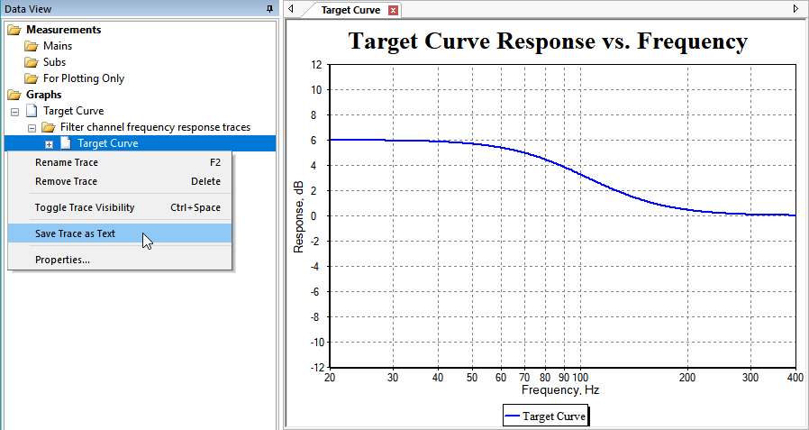
- Use the MSO tuning feature to adjust the curve to what you want.
- In the Data View, for the graph named Target Curve, select the trace named Target Curve.
- Right-click on the Target Curve trace and choose Save Trace as Text from the context menu as shown below.
- The text file that you save can then be imported as a target curve using this property page.
Any such target curve should be implemented using shelving EQ in the shared sub filter channel (input filters of a miniDSP). You shouldn't use PEQs to establish a target curve, unless the target curve itself looks like a PEQ, with a hump that becomes flat both above and below the frequency of the hump. MSO's shelving filters are best for this, while PEQs are best for fighting room modes.
The Group Weights Property Page
The last property page is called Group Weights. It is shown below.
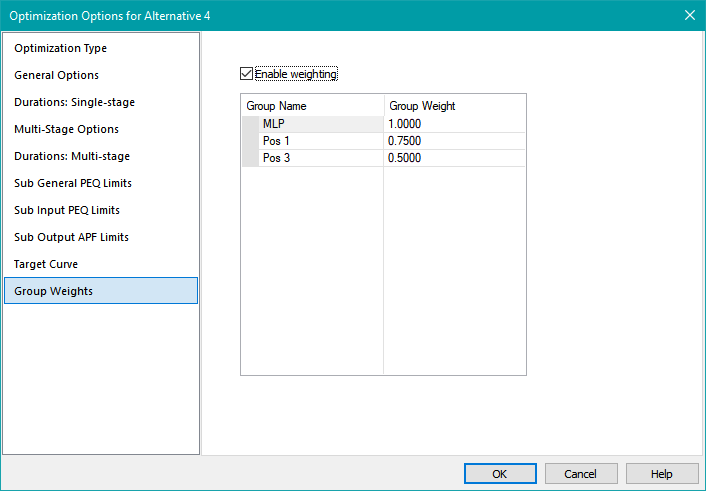
MSO v2 extends support of error weighting to all optimization types that combine error data from multiple listening positions. This means that error weighting is now supported for all optimization types except Flatten MLP response using only shared (input) filters.
The default value of all error weights is 1.0. When the Enable weighting checkbox is checked, you can edit the values of the error weights to be what you want. Since MSO internally normalizes these weights so that their sum is 1.0, only the relative values of the weights you enter are important.
If you enable weighting and specify weighting values that are not all equal to 1.0, subsequent toggling of the Enable weighting checkbox will alternately show all values of 1.0 when the checkbox is unchecked, and the error weights you previously entered when the checkbox is checked. If you subsequently press OK in the dialog when Enable weighting is unchecked, any custom weighting values you may have entered will still be saved, but they won't be used. This is to allow quickly switching between the weighted and unweighted conditions without needing to re-enter the error weights each time.