The Application Options Filter Property Pages
Setting Filter Parameter Defaults
The various property pages in the Filter Parameter Defaults category of the Application Options property sheet will be discussed here. These property pages share a set of common characteristics, which will be discussed first. Then the unique characteristics of each page will be described.
The Filter Parameter Defaults Property Pages
Usage of the Filter Parameter Defaults property pages is just one of several ways to set filter parameters. Filter parameters consist of both parameter limits and values. The limits represent the range over which the optimizer is allowed to adjust the parameter values during optimization.
The Filter Parameter Defaults property pages only affect the default values of the parameter limits. Furthermore, these parameter limits only apply to filters that have yet to be created, not existing filters. This creation can be done either indirectly from information on the Specify the Configuration Properties page of the Configuration Wizard, or directly when you manually add filters.
For a comprehensive description of all the different ways filter parameter values and their limits can be specified, see the topic in the "Tips and Tricks" section titled The Different Methods of Specifying Filter Parameter Values and Limits. That topic includes some details that aren't discussed here, but are nonetheless important aspects of the Filter Parameter Defaults property pages.
An example of a Filter Parameter Defaults property page is shown below.
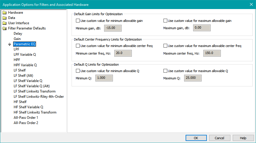
If you wish to change the default parameter limits from the program defaults, check the corresponding Use custom value for... checkbox. This will enable the corresponding edit control, allowing you to change the chosen limit value. Each filter parameter has both a minimum and maximum limit value. The Parametric EQ filters have three parameters, giving a total of six adjustments, consisting of the minimum and maximum allowable value for each of its three parameters. These limit values are further constrained by some absolute limits that are not user-adjustable. The purpose of these non-user-adjustable absolute limits is to prevent extreme values from being assigned to any parameter limits.
The changes that you make in the Filter Parameter Defaults property pages are stored in the Windows registry, so they apply to all projects. If you use a project on multiple computers, be sure the filter parameter defaults that are important to you are set to the same values on all the machines you're using for MSO. For most users, this usually consists of the default parameter limits for gain blocks, delay blocks and parametric EQ filters. Most of the rest of the filter types supported by MSO are for unusual situations.
The Individual Filter Parameter Defaults Property Pages
The options for the default parameter limits of all filter types supported by MSO are described below.
The Delay Parameter Defaults Property Page
The Delay Parameter Defaults property page is pictured below.
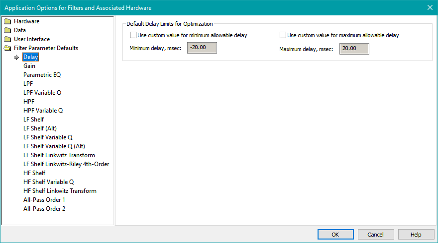
Notice that the default minimum delay shows a negative value, which appears to make no sense. However, allowing negative delays is an important technique used by MSO to help it find the best final delay values or AVR sub distance setting. This is done as follows.
- In MSO "sub-only" configurations, only the relative delays between subs matter. Consequently, if there are N subs, only N - 1 delays are needed. One sub always ends up with no delay, while the others are delayed relative to that one by positive delay values. However, it's not known in advance which sub should end up with zero delay for optimum performance. Allowing negative delays for the subs means that the N - 1 delays can initially be placed in any sub channels. After the optimization, if some subs have negative delays, a mathematical procedure is run that eliminates the negative delays, and in the process, may move some delay out of one channel and into another. When this process is complete, the problem of which sub should end up with zero delay is solved. This mathematical procedure is performed by both the Normalize Delays command and the filter report final delay values calculation. The former procedure actually moves the gain blocks around, while the latter just tells you what the delay of each sub should be, irrespective of which channels contain delay blocks. Thus the filter reports should be considered the final word in sub delay values.
- Since MSO delay values represent the change in delay from the measured condition, a negative delay in the MSO shared subwoofer channel has an important interpretation when used with "subs+mains" configurations. In this role, a negative delay is interpreted as "reduce the AVR sub delay relative to its value when the measurements were performed". This in turn means "make the sub distance setting in the AVR larger than what it was when the measurements were performed". The calculation of the required change in sub distance is automatically performed when the filter report final delay values are computed and displayed at the end of the filter report.
Because of these considerations, the minimum allowed delay should be negative, and should usually be set to the negative of the maximum allowed delay. Note that for the miniDSP 2x4 HD, the maximum delay allowed in the hardware is 80 msec, which way too large for practical applications. For this reason, it's suggested to keep the allowable delay range at the default of ±20 msec for the miniDSP 2x4 HD. This recommendation also applies to other DSP devices having extreme delay range adjustment.
The Gain Parameter Defaults Property Page
The image below shows the Gain Parameter Defaults property page.
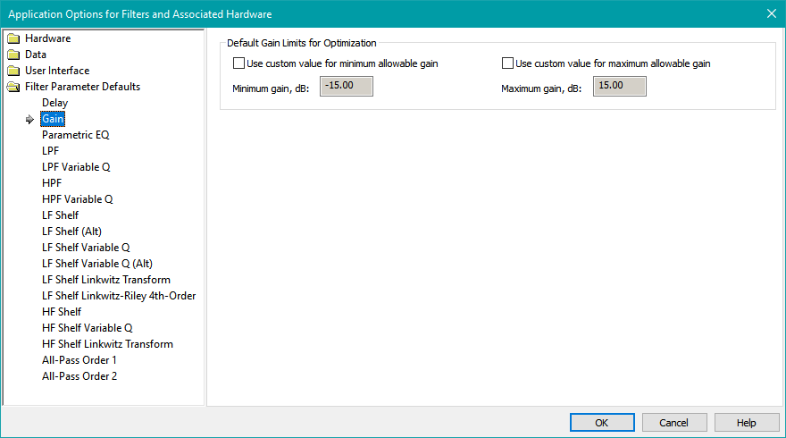
As with delay blocks, there are two principal ways that gain blocks are created.
- They are created automatically from information provided on the Specify the Configuration Properties page of the Configuration Wizard.
- The user can create them manually as described in Manually Adding Filters, Delays and Gains to Filter Channels.
However, unlike delay blocks, the parameter value limits of gain blocks created by the Configuration Wizard are not affected by the limits you specify on this property page. That is because the Configuration Wizard uses a special arrangement of gain blocks to help guarantee optimization success in a variety of circumstances without burdening the user with performing the needed calculations. This special gain block arrangement has the following characteristics.
- A gain block is always added to the shared sub channel regardless of whether the Add output-channel gain blocks checkbox is checked on the Specify the Configuration Properties page of the Configuration Wizard. It is created with a wide allowable parameter adjustment range of 0±24 dB. This wide allowable gain range guarantees that a wide range of reference levels can be used successfully without any gain block values bumping into their limits. Please note that the reference level in MSO has nothing whatsoever to do with AVR reference levels.
- If you choose the option in the Configuration Wizard to add output-channel gain blocks, then gain blocks with a narrow allowable parameter adjustment range are added to the individual sub channels. These gain blocks have an allowable gain range of 0±6 dB to minimize possible sub gain mismatch.
Because of this behavior of the Configuration Wizard, the gain value limits specified here are only used for manually-created gain blocks.
Even though gain blocks created either manually or by the Configuration Wizard can have positive values for their maximum gain, the computations of the filter report final gain values adjust the gains in such a way that only a shared gain block can have a positive gain in dB. Individual sub gain blocks are adjusted to have either 0 dB gain or a gain in dB that's negative (that is, an attenuation).
The Parametric EQ Parameter Defaults Property Page
The Parametric EQ Parameter Defaults property page is shown below.
This property page is used to establish parameter value limits for the following two filter types.
- Parametric EQ
- Parametric EQ (RBJ)
The PEQ parameter limits you can adjust are as below.
- Minimum and maximum allowable center frequency in Hz
- Minimum and maximum allowable gain at the center frequency
- Minimum and maximum allowable Q
When you run the Configuration Wizard, it creates Parametric EQ filters automatically from information provided on the Specify the Configuration Properties wizard page. Unless you change these filters, they will have the parameter limits specified in this property page. Also, if you manually create PEQ filters, their parameter limit values will be as you specify here. Setting these parameter limits on this property page is advantageous for several reasons.
- Certain DSP hardware limits the maximum value of Q that you can use with parametric EQ filters. For instance, the maximum Q value supported by current Behringer DSP amps is 10. By setting the maximum allowed Q to 10 in this property sheet, the Configuration Wizard will generate PEQ filters with maximum allowed Q values compatible with Behringer DSP amps.
- Some users prefer to limit the maximum Q that MSO can use for the PEQ filters to a value much less than what their hardware is capable of. This property page is a good place to establish such a limit for the maximum allowed Q value. Such lower Q limits may be appropriate for installations in homes using drywall construction. This type of construction leads to lossy sound reflections at the wall boundaries. These lossy reflections lead to lower values of Q needed to compensate for the reflections in the modal frequency region using PEQ filters.
- European users often have homes using older, more robust construction techniques that lead to less lossy sound reflections at the wall boundaries. These low-loss reflections increase the needed PEQ Q values to compensate for these reflections in the modal frequency region. The high absolute maximum limits allowed for Q in MSO were requested by a European user because of these considerations.
- For the maximum allowable gain parameter, a value of from 0 dB to 3 dB is common. Large boosts, if not carefully managed, can lead to clipping of the DSP device if its maximum output level can only reach a modest value.
For parametric EQ filters, the limits set on this property sheet are not necessarily the final story. On the PEQ Parameter Limits property pages of the Optimization Options property sheet, you can set parameter value limits for different groupings of PEQs all at once at any time. That behavior is in contrast to how the parameter limits specified in these Filter Parameter Defaults property pages work. These property pages only affect the parameter value limits for newly created filters. The parameter limits specified in the PEQ Parameter Limits property pages of the Optimization Options property sheet can alter the filter parameter limits at any time after these filters have been created. Be sure to read the documentation for the PEQ Parameter Limits property pages for complete information.
The LPF Parameter Defaults Property Page
The LPF Parameter Defaults property page is illustrated below.
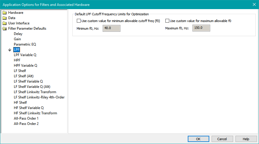
This property page is used to establish parameter value limits for the following filter types.
- LPF 6 dB/oct
- LPF Butterworth 12 dB/oct
- LPF Bessel 12 dB/oct
- LPF Linkwitz-Riley 12 dB/oct
- LPF Butterworth 18 dB/oct
- LPF Butterworth 24 dB/oct
- LPF Bessel 24 dB/oct
- LPF Linkwitz-Riley 24 dB/oct
- LPF Butterworth 48 dB/oct
- LPF Linkwitz-Riley 48 dB/oct
The LPF parameter limits you can adjust are as below.
- Minimum and maximum allowable cutoff frequency in Hz
For 6 dB/oct filters, as well as Butterworth filters of all order, the cutoff frequency is the -3 dB frequency. For Linkwitz-Riley filters of all order, the cutoff frequency is the -6 dB frequency. For Bessel filters, the attenuation at the cutoff frequency varies with order.
The LPF Variable Q Parameter Defaults Property Page
The LPF Variable Q Parameter Defaults property page is shown below.

This property page is used to establish parameter value limits for the following filter type.
- LPF Variable Q 12 dB/oct
The parameter limits you can adjust are as below.
- Minimum and maximum allowable cutoff frequency in Hz
- Minimum and maximum allowable Q
This Variable Q 12 dB/oct LPF filter type allows you to implement several LPF types as special cases. These are as follows.
- An LPF Butterworth 12 dB/oct filter, by using a Q value of 1/sqrt(2) = 0.707
- An LPF Bessel 12 dB/oct filter, by using a Q value of 1/sqrt(3) = 0.577
- An LPF Linkwitz-Riley 12 dB/oct filter, by using a Q value of 0.5
When a Butterworth 12 dB/oct filter (Q = 0.707) is implemented with this filter type, its cutoff frequency is the -3 dB frequency. When a Linkwitz-Riley 12 dB/oct filter (Q = 0.5) is implemented, its cutoff frequency is the -6 dB frequency. For other values of Q, the attenuation at the cutoff frequency varies.
The HPF Parameter Defaults Property Page
The HPF Parameter Defaults property page is illustrated below.
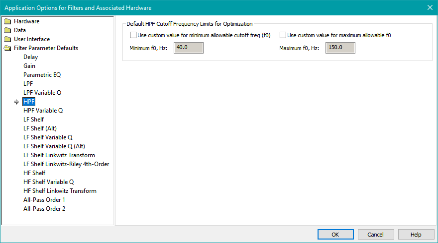
This property page is used to establish parameter value limits for the following filter types.
- HPF 6 dB/oct
- HPF Butterworth 12 dB/oct
- HPF Bessel 12 dB/oct
- HPF Linkwitz-Riley 12 dB/oct
- HPF Butterworth 18 dB/oct
- HPF Butterworth 24 dB/oct
- HPF Bessel 24 dB/oct
- HPF Linkwitz-Riley 24 dB/oct
- HPF Butterworth 48 dB/oct
- HPF Linkwitz-Riley 48 dB/oct
The HPF parameter limits you can adjust are as below.
- Minimum and maximum allowable cutoff frequency in Hz
For 6 dB/oct filters, as well as Butterworth filters of all order, the cutoff frequency is the -3 dB frequency. For Linkwitz-Riley filters of all order, the cutoff frequency is the -6 dB frequency. For Bessel filters, the attenuation at the cutoff frequency varies with order.
The HPF Variable Q Parameter Defaults Property Page
The HPF Variable Q Parameter Defaults property page is shown below.
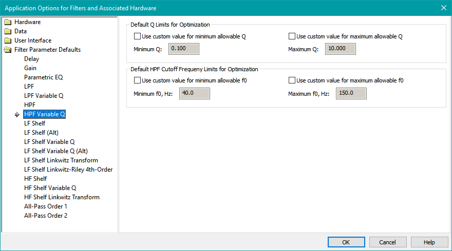
This property page is used to establish parameter value limits for the following filter type.
- HPF Variable Q 12 dB/oct
The parameter limits you can adjust are as below.
- Minimum and maximum allowable cutoff frequency in Hz
- Minimum and maximum allowable Q
This Variable Q 12 dB/oct LPF filter type allows you to implement several HPF types as special cases. These are as follows.
- An HPF Butterworth 12 dB/oct filter, by using a Q value of 1/sqrt(2) = 0.707
- An HPF Bessel 12 dB/oct filter, by using a Q value of 1/sqrt(3) = 0.577
- An HPF Linkwitz-Riley 12 dB/oct filter, by using a Q value of 0.5
When a Butterworth 12 dB/oct filter (Q = 0.707) is implemented with this filter type, its cutoff frequency is the -3 dB frequency. When a Linkwitz-Riley 12 dB/oct filter (Q = 0.5) is implemented, its cutoff frequency is the -6 dB frequency. For other values of Q, the attenuation at the cutoff frequency varies.
The LF Shelf Parameter Defaults Property Page
The LF Shelf Parameter Defaults property page is shown below.
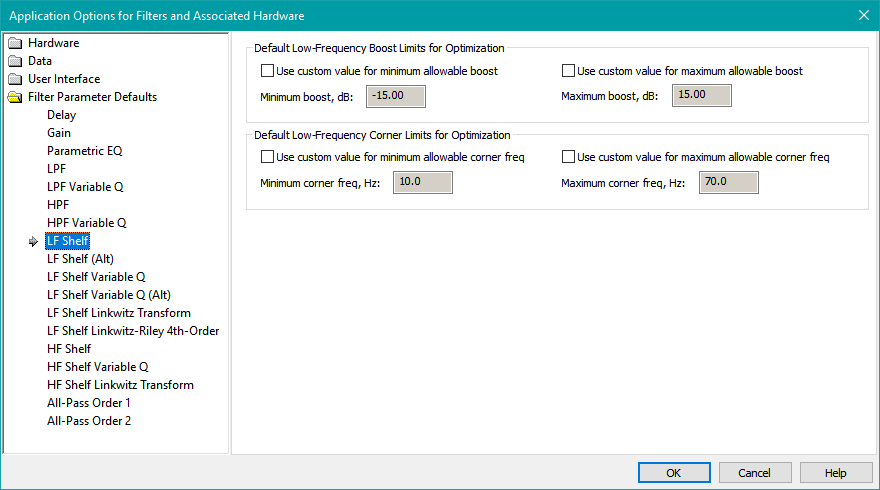
This property page is used to establish parameter value limits for the following filter types.
- LF Shelf Order 1
- LF Shelf Order 2
The parameter limits you can adjust are as below.
-
Minimum and maximum allowable LF boost in dB
- To allow an LF cut, use a negative value for the minimum allowable LF boost.
- Minimum and maximum allowable LF corner frequency in Hz
The LF Shelf Order 1 and LF Shelf Order 2 filters are for compatibility with the LS6 and LS12 filter types respectively of the Behringer DSP amps and DCX2496 processor. The LF corner frequency in Hz is best understood in the case where the boost in dB is very large. In such cases, the LF corner frequency is approximately the frequency for which the LF boost is 3 dB less than the maximum LF boost. This convention matches what Behringer uses in their DSP control software. See the Behringer filter compatibility table for more information about compatibility of MSO and Behringer filter types. An LF Shelf Order 2 filter is equivalent to an LF Shelf Order 2 Variable Q filter having a Q value of 1/sqrt(2) = 0.707.
Users of miniDSP hardware should use the LF shelf filters with "(Alt)" in their names instead. These filters use a "center frequency" convention that is more easily understood. See the documentation for the parameter defaults property pages for those filter types for more information about the meaning of the center frequency.
The LF Shelf (Alt) Parameter Defaults Property Page
The LF Shelf Parameter Defaults property page is shown below.
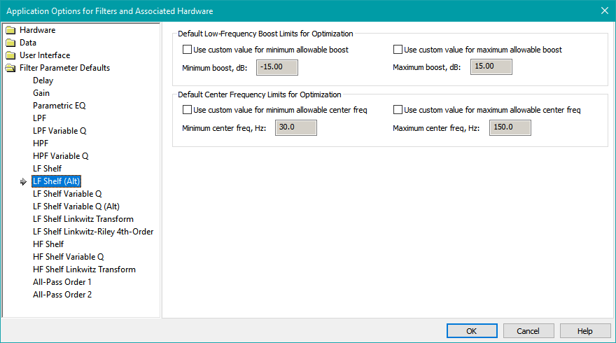
This property page is used to establish parameter value limits for the following filter types.
- LF Shelf Order 1 (Alt)
- LF Shelf Order 2 (Alt)
The parameter limits you can adjust are as below.
-
Minimum and maximum allowable LF boost in dB
- To allow an LF cut, use a negative value for the minimum allowable LF boost.
- Minimum and maximum allowable center frequency in Hz
The center frequency of the LF Shelf Order 1 (Alt) and LF Shelf Order 2 (Alt) filter types is defined as that frequency for which the boost (or cut) in dB is one-half the ultimate low-frequency boost (or cut) in dB. For instance, if the LF boost in dB were specified as 6 dB, that shelving filter will have a boost in dB that approaches 6 dB as the frequency approaches zero. If the center frequency were specified as 50 Hz, then that filter's boost value would be 3 dB at 50 Hz. An LF Shelf Order 2 (Alt) filter is equivalent to an LF Shelf Order 2 Variable Q (Alt) filter having a Q value of 1/sqrt(2) = 0.707. This gives a so-called "maximally flat" behavior.
The LF Shelf Variable Q Parameter Defaults Property Page
The LF Shelf Variable Q Parameter Defaults property page is shown below.
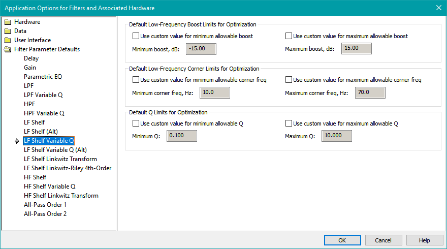
This property page is used to establish parameter value limits for the following filter type.
- LF Shelf Order 2 Variable Q
The parameter limits you can adjust are as below.
-
Minimum and maximum allowable LF boost in dB
- To allow an LF cut, use a negative value for the minimum allowable LF boost.
- Minimum and maximum allowable LF corner frequency in Hz
- Minimum and maximum allowable Q
The LF corner frequency in Hz is best understood in the case where the boost in dB is very large. In such cases, the LF corner frequency is approximately the frequency for which the LF boost is 3 dB less than the maximum LF boost.
Usage of this filter type is not recommended, as equivalent behavior can be achieved using the LF Shelf Order 2 Variable Q (Alt) filter type described below. The LF shelving filters with an "(Alt)" designation use a center frequency conventions that's easier to understand than the corner frequency convention described above for this filter type.
The LF Shelf Variable Q (Alt) Parameter Defaults Property Page
The LF Shelf Variable Q (Alt) Parameter Defaults property page is shown below.
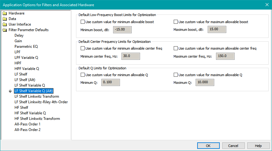
This property page is used to establish parameter value limits for the following filter type.
- LF Shelf Order 2 Variable Q (Alt)
The parameter limits you can adjust are as below.
-
Minimum and maximum allowable LF boost in dB
- To allow an LF cut, use a negative value for the minimum allowable LF boost.
- Minimum and maximum allowable center frequency in Hz
- Minimum and maximum allowable Q
The center frequency of the LF Shelf Order 2 Variable Q (Alt) filter type is defined as that frequency for which the boost (or cut) in dB is one-half the ultimate low-frequency boost (or cut) in dB. For instance, if the LF boost in dB is specified as 6 dB, that shelving filter will have a boost in dB that approaches 6 dB as the frequency approaches zero. If the center frequency were specified as 50 Hz, then that filter's boost value would be 3 dB at 50 Hz.
This is the recommended LF shelving filter type to use in the MSO shared sub filter channel to achieve a target curve with a rising low-frequency response. See the target curve example for more information about this filter type and how to use it to generate and establish a target curve.
The LF Shelf Linkwitz Transform Parameter Defaults Property Page
The LF Shelf Linkwitz Transform Parameter Defaults property page is shown below.
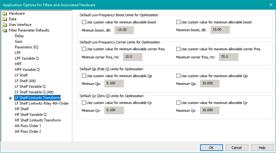
This property page is used to establish parameter value limits for the following filter type.
- LF Shelf Linkwitz Transform
The parameter limits you can adjust are as below.
-
Minimum and maximum allowable LF boost in dB
- To allow an LF cut, use a negative value for the minimum allowable LF boost.
- Minimum and maximum allowable LF corner frequency in Hz
- Minimum and maximum allowable Qp ("pole Q")
- Minimum and maximum allowable Qz ("zero Q")
The LF boost in dB of a Linkwitz Transform filter is equal to the boost you specify for this parameter, while the response approaches 0 dB (no boost or cut) at high frequencies.
The Linkwitz Transform filter is not usually used for subwoofer applications, except possibly by subwoofer vendors who use the advertised LF cutoff frequency of sealed subs for marketing purposes. It can extend the anechoic LF response of a sub by applying LF boost and setting Qp and Qz appropriately, using Thiele-Small theory. For most subwoofer applications, it's best to let the room modes boost the LF response below the anechoic cutoff frequency of the sealed sub (typically 40 Hz), then use PEQs or LF Shelf Variable Q (Alt) filters to clean up any resulting in-room response irregularities. The LF Shelf Linkwitz Transform filter is provided for completeness.
The LF Shelf Linkwitz-Riley 4th-Order Parameter Defaults Property Page
The LF Shelf Linkwitz-Riley 4th-Order Parameter Defaults property page is shown below.
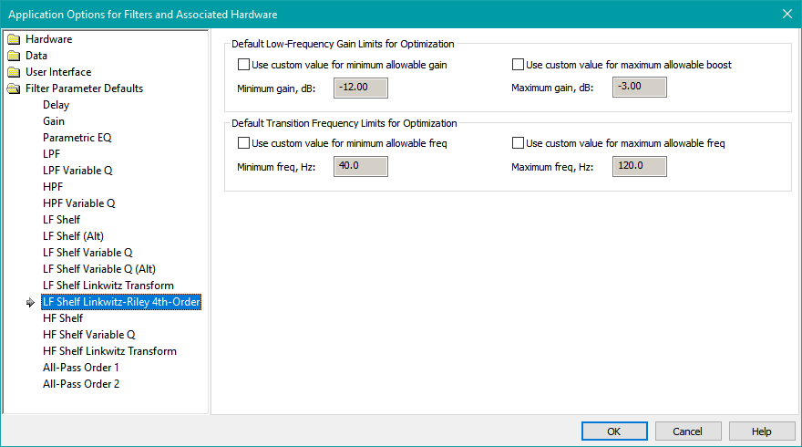
This property page is used to establish parameter value limits for the following filter type.
- LF Shelf Linkwitz-Riley Fourth-Order
The parameter limits you can adjust are as below.
-
Minimum and maximum allowable LF gain in dB
- For this filter type, both minimum and maximum LF gain must be negative, as it's an LF shelf that provides only attenuation.
- Minimum and maximum allowable transition frequency in Hz
This is an experimental filter type created by the MSO author, meant only for main speakers, not subs. It is intended to be used in systems without a "classic" crossover. The complex summation of a fourth-order Linkwitz-Riley (LR4) LPF applied to the subs (with levels suitably set), and this filter applied to the main speakers results in the same all-pass response as that achieved using an LR4 LPF on the subs and an LR4 HPF on the main speakers. The difference is that using this filter on the main speakers instead of an LR4 HPF gives an overlap in the frequency range used by main speakers and subs, while avoiding the response hump that would otherwise occur without an attenuating LF shelf applied to the main speakers. The transition frequency of this filter must be the same as the -6 dB frequency of the LR4 LPF that's assumed to be applied to the subs.
This filter is only for experimental use.
The HF Shelf Parameter Defaults Property Page
The HF Shelf Parameter Defaults property page is shown below.
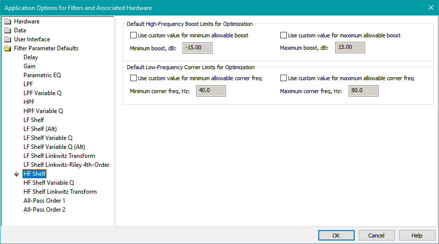
This property page is used to establish parameter value limits for the following filter types.
- HF Shelf Order 1
- HF Shelf Order 2
The parameter limits you can adjust are as below.
-
Minimum and maximum allowable HF boost in dB
- To allow an HF cut, use a negative value for the minimum allowable HF boost.
- Minimum and maximum allowable LF corner frequency in Hz
The LF corner frequency in Hz can be thought of as the frequency at which the response begins to "bend upward" toward high frequencies if there is an HF boost, or "bend downward" toward high frequencies if there is an HF cut.
HF shelving filters have an LF gain that's fixed at 0 dB, while both boost and cut at high frequencies are possible. For Behringer compatibility, see the Behringer filter compatibility table. There you'll find that the HF corner frequency specified in the MSO filter reports must be used with Behringer devices. The LF corner frequency cannot be used directly with Behringer devices.
The HF shelving filters are intended to compensate for either known inductance-related HF roll-off of subs, or subs whose amplifiers use LPFs that can't be disabled. They shouldn't be used to compensate for roll-off introduced in measurements due to incorrect sub or AVR setup.
The HF Shelf Variable Q Parameter Defaults Property Page
The HF Shelf Variable Q Parameter Defaults property page is shown below.
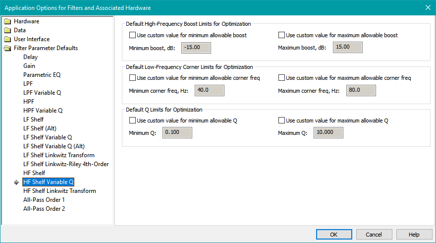
This property page is used to establish parameter value limits for the following filter type.
- HF Shelf Order 2 Variable Q
The parameter limits you can adjust are as below.
-
Minimum and maximum allowable HF boost in dB
- To allow an HF cut, use a negative value for the minimum allowable HF boost.
- Minimum and maximum allowable LF corner frequency in Hz
- Minimum and maximum allowable Q
The LF corner frequency in Hz can be thought of as the frequency at which the response begins to "bend upward" toward high frequencies if there is an HF boost, or "bend downward" toward high frequencies if there is an HF cut. HF shelving filters have an LF gain that's fixed at 0 dB, while both boost and cut at high frequencies are possible.
The HF shelving filters are intended to compensate for either known inductance-related HF roll-off of subs, or subs whose amplifiers use LPFs that can't be disabled. They shouldn't be used to compensate for roll-off introduced in measurements due to incorrect sub or AVR setup.
The HF Shelf Linkwitz Transform Parameter Defaults Property Page
The HF Shelf Linkwitz Transform Parameter Defaults property page is shown below.
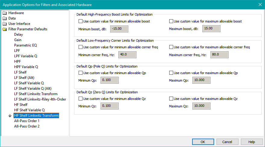
This property page is used to establish parameter value limits for the following filter type.
- HF Shelf Linkwitz Transform
The parameter limits you can adjust are as below.
-
Minimum and maximum allowable HF boost in dB
- To allow an HF cut, use a negative value for the minimum allowable HF boost.
- Minimum and maximum allowable LF corner frequency in Hz
- Minimum and maximum allowable Qp ("pole Q")
- Minimum and maximum allowable Qz ("zero Q")
The HF boost in dB of an HF Shelf Linkwitz Transform filter is equal to the boost you specify for this parameter, while the response approaches 0 dB (no boost or cut) at low frequencies. The LF corner frequency in Hz can be thought of as the frequency at which the response begins to "bend upward" toward high frequencies if there is an HF boost, or "bend downward" toward high frequencies if there is an HF cut.
The HF shelving filters are intended to compensate for either known inductance-related HF roll-off of subs, or subs whose amplifiers use LPFs that can't be disabled. They shouldn't be used to compensate for roll-off introduced in measurements due to incorrect sub or AVR setup.
Voice coil inductance of subs can sometimes cause an HF roll-off whose shape doesn't lend itself well to correction by the more conventional HF Shelf Variable Q filters. An HF Shelf Linkwitz Transform filter has more adjustable parameters, so it's often possible to get a better correction than can be obtained with an HF Shelf Variable Q filter. Both of these filter types use only a single biquad, so this performance improvement is obtained without an increase in DSP resource usage. See the Equalizing Sub High-Frequency Roll-Off optimization example for details.
The All-Pass Order 1 Parameter Defaults Property Page
The All-Pass Order 1 Parameter Defaults property page is shown below.
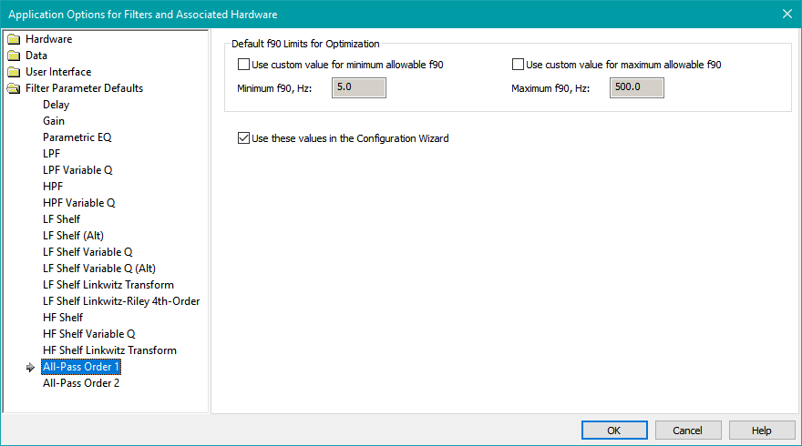
This property page is used to establish parameter value limits for the following filter type.
- All-Pass First-Order
The parameter limits you can adjust are as below.
- Minimum and maximum allowable values of f90 (center frequency in Hz)
Other options you can set:
- Use these values in the Configuration Wizard allows you to control the default parameter limits set by the Configuration Wizard when it creates a configuration having first-order all-pass filters.
All-pass filters have a magnitude response that's flat at 0 dB over all frequencies, and a phase shift that varies with frequency. The phase shift of first-order all-pass filters is 0 degrees at high frequencies, and goes to +180 degrees at low frequencies. These filters have a single parameter, the center frequency. This frequency is sometimes called f90, as it is the frequency for which the phase shift from input to output is +90 degrees. The optimizer can vary this center frequency over the range you supply here for the minimum and maximum center frequency values.
There has been increasing interest in all-pass filters in connection with the SPL maximization feature introduced in MSO v2. But even for such applications, first-order all-pass filters aren't often needed. They also use up a single biquad - the same usage as a second-order all-pass filter - so they don't make efficient use of DSP resources.
The All-Pass Order 2 Parameter Defaults Property Page
The All-Pass Order 2 Parameter Defaults property page is shown below.
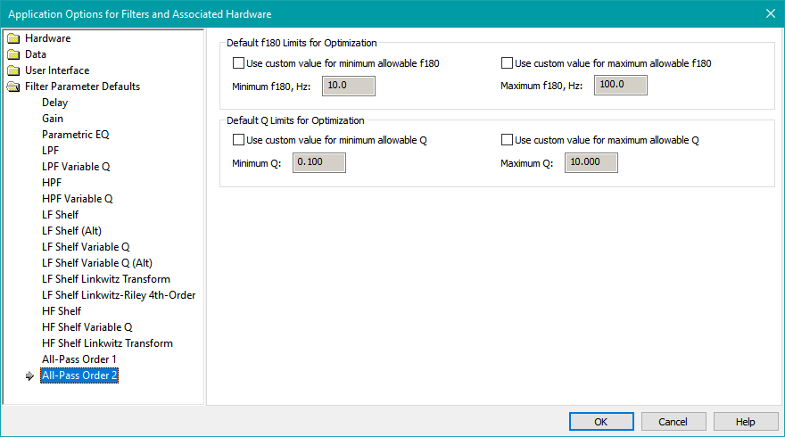
This property page is used to establish parameter value limits for the following filter type.
- All-Pass Second-Order
The parameter limits you can adjust are as below.
- Minimum and maximum allowable values of f180 (center frequency in Hz)
- Minimum and maximum allowable values of Q
Other options you can set:
- Use these values in the Configuration Wizard allows you to control the default parameter limits set by the Configuration Wizard when it creates a configuration having second-order all-pass filters.
All-pass filters have a magnitude response that's flat at 0 dB over all frequencies, and a phase shift that varies with frequency. The phase shift of second-order all-pass filters is 0 degrees at high frequencies, and goes to +360 degrees at low frequencies. Second-order all-pass filters have two parameters: the center frequency and Q. The center frequency is sometimes called f180, as it is the frequency for which the phase shift from input to output is +180 degrees. The optimizer can vary the center frequency and Q over the ranges you supply here for the minimum and maximum center frequency and Q values.
The value of Q affects the flatness of the group delay. A Q value of 1/sqrt(3) = 0.577 gives a Bessel all-pass filter, which has a so-called "maximally flat group delay". Values of Q higher than this will yield an all-pass filter with a peak in its group delay before it drops toward zero at high frequencies, while Q values less than 1/sqrt(3) will give a group delay that gently sags toward zero at high frequencies.
There has been increasing interest in all-pass filters in connection with the SPL maximization feature introduced in MSO v2. Second-order all-pass filters have important usage in this application, so the ability to add them is provided by the Configuration Wizard.