Getting Filter, Delay and Gain Information From MSO Into the DSP Device
Now that we're satisfied with the results we're getting from the Iteration 4 configuration, we are almost ready to export MSO's filter information and import it into our miniDSP device. As we've been doing throughout this tutorial, we'll assume the use of a miniDSP 2x4 HD device. But before exporting the data from MSO, it's a good idea to make sure we've entered the correct information about this device into MSO.
Verifying the DSP Hardware Information
From the main menu, choose Tools, Application Options, Hardware. You should see the property page shown below.
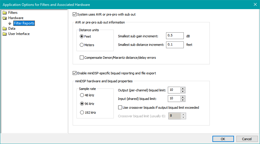
Make sure that Enable miniDSP-specific biquad reporting and file export is checked. Set the sample rate to 96 kHz, and ensure that Output (per-channel) biquad limit and Input (shared) biquad limit are both set to 10. If an incorrect sample rate is entered, there will be drastic errors in the filter responses that will make the results invalid. The correct sample rate is 96 kHz for the miniDSP 2x4 HD, and for the non-HD 2x4 units it should be 48 kHz.
A Brief Explanation of Biquads
Internal to the miniDSP devices themselves, each PEQ in MSO gets implemented by a so-called biquad. The usage of biquad information to specify the implementaton of internal filters is referred to as "advanced biquad filter programming" by miniDSP. They have an article about it on their web site. Also, in the 2x4 HD user manual, section 6.6 describes custom biquad programming.
In MSO, a PEQ is described by three parameters: the center frequency, the boost/cut value at the center frequency, and the Q. In the miniDSP implementation, each biquad is described by five coefficients called a1, a2, b0, b1 and b2. There is a formula for converting the PEQ parameters described by the center frequency, the boost/cut value at the center frequency, and the Q, and converting them to their equivalent biquad coefficients a1, a2, b0, b1 and b2. MSO uses this formula to find the required biquad coefficients for each PEQ in a given channel of a configuration.
But most importantly, the custom biquad programming feature of miniDSP devices allows us to specify all the filters in any miniDSP channel in one step, rather than having to tediously specify the parameters of each PEQ individually.
Exporting Biquad Text of All Channels at Once
The easiest way to export biquad text is to do so for all channels of a configuration at once. This technique is described in detail in the reference manual. That is the recommended technique.
You can also export the biquads of a single channel at a time. That method is described below. If you export all channels at once, you can skip the section below.
Exporting Biquad Text of a Single Channel
Earlier in the tutorial, some tips were presented regarding the naming of subs and listening positons, along with using the miniDSP channel labeling feature to give each DSP channel a name that matches, or is very similar to, the name you chose for the sub that's hooked up to that channel. Following these guidelines means that it will be easy to match up the exported MSO biquad data with the miniDSP channel into which you will import it.
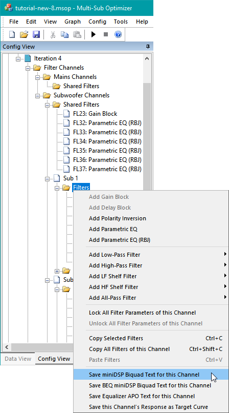
Open up the tutorial-new-8.msop project. In the Config View, make sure the Iteration 1, Baseline, Iteration 2 and Iteration 3 tree nodes are all collapsed, and expand the Iteration 4 tree node. Under the Sub 1 channel, select the Filters node. Right-click on it and choose Save miniDSP Biquad Text for this Channel per the figure below.
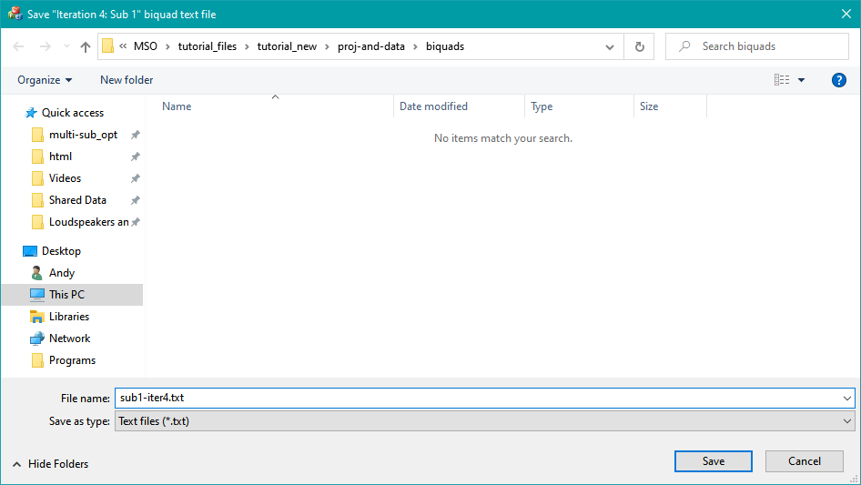
You'll be presented with a standard Windows File Save dialog as shown below. Name the file sub1-iter4.txt to denote the sub channel and configuration name.
Repeat the process for each of the Sub 2, Sub 2 and Sub 2 channels, naming the exported text files sub2-iter4.txt, sub3-iter4.txt and sub4-iter4.txt respectively.
Right-click on the Shared Filters node under Subwoofer Channels and again choose Save miniDSP Biquad Text for this Channel. When prompted for a file name, choose input-iter4.txt to denote that the shared filters for Iteration 4 go into the input channel of the miniDSP. Now you'll have five exported biquad text files, one for each individual sub channel and one for the input channel. Let's have a look at one of these text files, sub1-iter4.txt.
biquad1,
b0=0.999989166838556,
b1=-1.999886290469939,
b2=0.999898778847783,
a1=1.999886290469939,
a2=-0.999887945686339,
biquad2,
b0=0.999974492810956,
b1=-1.999869158863082,
b2=0.999896995587342,
a1=1.999869158863082,
a2=-0.999871488398298,
biquad3,
b0=0.997537256078264,
b1=-1.993389575715254,
b2=0.995909420023960,
a1=1.993389575715254,
a2=-0.993446676102224,
biquad4,
b0=1.000056124674351,
b1=-1.999704743908548,
b2=0.999671780457762,
a1=1.999704743908548,
a2=-0.999727905132113,
biquad5,
b0=1.000132233388628,
b1=-1.999260172246128,
b2=0.999226693378877,
a1=1.999260172246128,
a2=-0.999358926767506,
biquad6,
b0=1.000081628737822,
b1=-1.999426035048186,
b2=0.999497852267782,
a1=1.999426035048186,
a2=-0.999579481005603
This isn't particularly interesting or enlightening, but it does at least show that there are six biquads, corresponding to the six PEQs in each channel. If you're curious, you can find out which PEQ is implemented by which biquad by right-clicking on Iteration 4 in the Config View and choosing Show Filter Report. If you scroll down in the filter report a bit, you'll find the following.
DSP Filter Channel Information:
Sample frequency 96000 Hz
Filter/biquad info for Sub 1:
FL1: Parametric EQ (RBJ) (biquad1)
FL2: Parametric EQ (RBJ) (biquad2)
FL3: Parametric EQ (RBJ) (biquad3)
FL4: Parametric EQ (RBJ) (biquad4)
FL24: Parametric EQ (RBJ) (biquad5)
FL25: Parametric EQ (RBJ) (biquad6)
This shows the correspondence between biquads and PEQs.
Importing the Biquad Text Into the miniDSP 2x4 HD
The format of the biquad text files shown above is exactly the same as what REW uses. This means that you can refer to miniDSP's documentaion for instructions showing how to import these files. In the miniDSP 2x4 HD manual, this is in section 6.6.2, Using custom biquad programming, under Parametric EQ file import (REW integration). They also have a dedicated web page with instructions for REW file import.
For more detail of how to import the biquad text files into the miniDSP 2x4 HD, see Jeff Mery's video covering miniDSP data entry.
Setting the Individual Channel Delays
If you haven't already done so, run a filter report on the Iteration 4 channel. Click on the report text and press Ctrl+End to get to the end of the report. You'll see the following.
Delay settings:
Sub 1 delay: 17.17 msec
Sub 2 delay: 0.00 msec
Sub 3 delay: 16.60 msec
Sub 4 delay: 17.54 msec
These need to be manually entered into the miniDSP software. Section 6.5.9 of the 2x4 HD owner's manual, Time delay, describes the process. The instructions are quoted below.
"A delay of up to 80 ms can be applied to each output channel. To set the delay, click in the delay entry box for a channel. The delay value can be entered numerically, and the up and down arrows can be used to change the delay in small (0.01 ms) increments. The maximum time delay of 80 ms corresponds to a distance of approximately 27.5 meters (about 90 feet)."
Setting the Sub Gains
At the end of the filter report, you'll also find the following text.
Final gain and delay/distance settings:
Complete gain settings for chosen fixed SPL target level (optional):
No change to AVR sub out trim gain
Sub 1 gain: -0.30 dB
Sub 2 gain: -5.98 dB
Sub 3 gain: -5.58 dB
Sub 4 gain: -0.30 dB
Minimal gain settings, neglecting SPL target:
Sub 1 gain: -0.00 dB
Sub 2 gain: -5.68 dB
Sub 3 gain: -5.28 dB
Sub 4 gain: 0.00 dB
Which of these alternatives should we choose? The first one is for subs+mains configurations, where the level of the subs when treated as one is critical for correct integration of the mains and subs. For subs considered by themselves, as is done when using sub-only configurations, the absolute level of the subs won't matter until some later time when we integrate them with the main speakers. Therefore, choose the gain settings specified under Minimal gain settings, neglecting SPL target.
For setting the gains of each channel, refer to section 6.5.3 of the 2x4 HD owner's manual. These instructions are quoted below.
"The gain of each channel can be adjusted by moving the Gain Adjustment slider, or by typing the desired gain into the Current Gain text box. The maximum gain setting is 12 dB, and the minimum gain setting is –72 dB. (0 dB, the default, is unity gain or no change in level.)"
Use the instructions above to set the Sub 2 and Sub 3 gains to -5.68 dB and -5.28 dB respectively.
Why Specify a Reference Level if We're Just Going to Throw it Away?
Recall that earlier in the tutorial, we specified a reference level in the Method property page of the Optimization Options property sheet. Yet here we are neglecting it in specifying only the relative sub gains. It's reasonable to wonder why. The question is best answered by considering what would happen if the algorithm did not try to reach a specified reference level. In that case, the algorithm named Minimize seat-to-seat variation, also on the Method property page of the Optimization Options property sheet, would try to do just that, without regard to the absolute level of the response. If that were the case, the user would see the traces jump up and down in level during the optimization with no apparent rhyme or reason. This would rightfully be perceived as a bug. The algorithm uses a reference level so that as it heads toward a solution during the optimization, the absolute level approaches the target value.
Wrapping Up
We now have all the filter, gain and delay information entered into the miniDSP 2x4 HD. This is a good time to measure your system to verify that the final measured performance matches what MSO predicts.