Interpreting Filter Report Data
Before entering our filter, gain, and delay settings into our DSP device, we'll need to run an MSO Filter Report. But before running a filter report, we'll need to tell MSO some things about our AVR and DSP device so it can tailor the filter report to match the capabilities of our hardware.
To do this, choose Tools, Application Options from the main menu, then click on Hardware to show the property page for specifying your hardware properties. This property page is shown below.
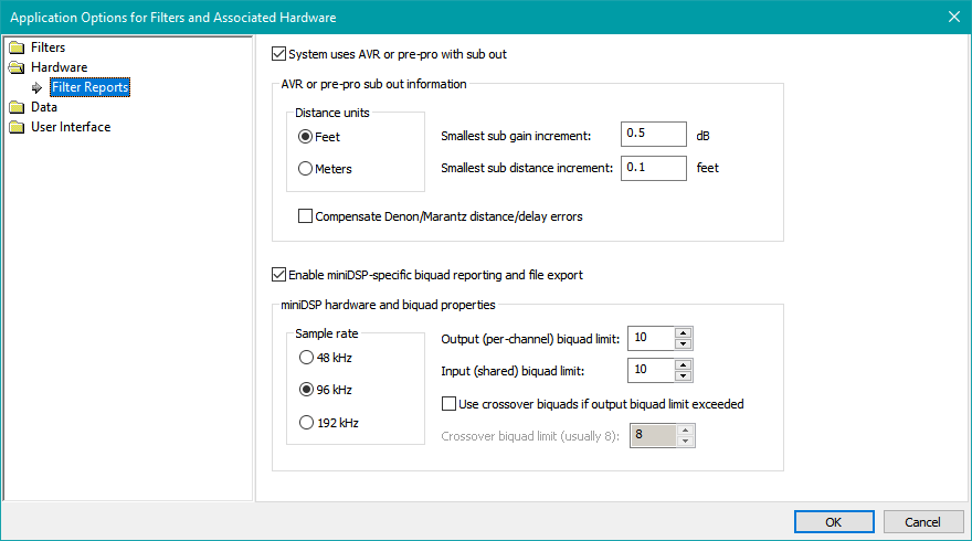
Checking System uses AVR or pre-pro with sub out is optional for this tutorial. It is only necessary when using a "subs+mains" configuration. For such configurations, MSO reports the required final AVR sub distance and trim values using the distance and gain step resolutions you specify.
The AVR or pre-pro sub out information options above are typical settings. The units for distance setting are configured to use feet, and the smallest sub distance increment is set to 0.1 feet. These options are provided so that MSO can tell you how much to change your AVR's sub distance setting after an optimization (if applicable). Also, MSO tries to fine-tune the DSP delay settings to make up for the limited delay resolution of a typical AVR, so that the actual delays of your system after data entry are as close as possible to what MSO calculates. A similar situation applies to the AVR sub gain adjustment resolution (Smallest sub gain increment) specified here. MSO tries to fine-tune the DSP gain settings to make up for the limited resolution of the AVR sub level adjustment.
The Enable miniDSP-specific biquad reporting and file export must be checked in order to specify the biquad export options for your DSP hardware.
The miniDSP hardware and biquad properties are configured above for the miniDSP 2x4 HD. It's absolutely essential to select the correct sample rate here, or else the actual filters loaded into the miniDSP will be invalid. The miniDSP 2x4 HD uses a 96 kHz sample rate, while the 2x4 non-HD miniDSP units use 48 kHz. For compatibility with the miniDSP 2x4 HD device, enter a value of 10 for the input and output biquad limit as shown in the illustration above. The biquad limit for the non-HD miniDSP 2x4 devices depends on the software plugin used. Consult the miniDSP documentation for details. The Use crossover biquads if output biquad limit exceeded option is an advanced feature that we won't discuss here. Leave it unchecked.
These settings are stored in the Windows registry, not the project, so they persist across projects. For this reason, if you move a project from one machine to another, you should make sure these settings are all correct on that machine.
If you want your filter reports to match what's shown in this tutorial, you should configure both the AVR and DSP settings to match the figure above.
Showing the Filter Report
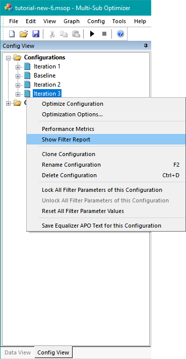
In the Config View, right-click on the Iteration 3 node and choose Show Filter Report as shown in the figure below.
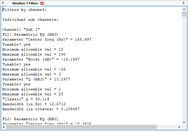
A tabbed text view with filter information will appear as in the figure below.
Looking Closely at the Gain Values
Click in the text view and press Ctrl+End to get to the end of the text. The information about gain and delay blocks gets consolidated at the end of the filter report, while detailed information about filters (not usually needed) is at the beginning. The important information about gain and delay blocks has been copied below for the Iteration 3 configuration.
Raw uncorrected gain and delay values:
These gain and delay values are for reference only.
For final gain and delay values, see
"Final gain and delay/distance settings" at end of report.
Unadjusted gain values of all gain blocks:
FL5 (Sub 1, gain block) gain: -5.11 dB
FL11 (Sub 2, gain block) gain: -5.25 dB
FL17 (Sub 3, gain block) gain: -3.29 dB
FL23 (Sub 4, gain block) gain: 10.99 dB
Unadjusted delay values of all delay blocks:
FL6 (Sub 1, delay block) delay: -4.25 msec
FL12 (Sub 2, delay block) delay: -1.00 msec
FL18 (Sub 3, delay block) delay: -8.44 msec
Final gain and delay/distance settings:
Complete gain settings for chosen fixed SPL target level (optional):
Increase AVR sub out trim gain by 11.00 dB
Sub 1 gain: -16.11 dB
Sub 2 gain: -16.25 dB
Sub 3 gain: -14.29 dB
Sub 4 gain: -0.01 dB
Minimal gain settings, neglecting SPL target:
Sub 1 gain: -16.10 dB
Sub 2 gain: -16.24 dB
Sub 3 gain: -14.29 dB
Sub 4 gain: 0.00 dB
Delay settings:
Sub 1 delay: 4.18 msec
Sub 2 delay: 7.44 msec
Sub 3 delay: 0.00 msec
Sub 4 delay: 8.44 msec
That's a lot of information, but we'll break it down into smaller pieces. First, we'll focus on the gain values of the gain blocks FL5, FL11, FL17 and FL23. These gain blocks, after a little algebra that MSO does for you, represent gain values that we'll manually enter into the miniDSP. I've selected the information from these four gain blocks and reproduced it below.
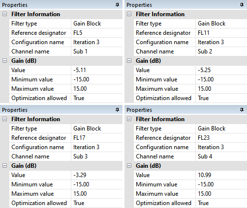
Unadjusted gain values of all gain blocks:
FL5 (Sub 1, gain block) gain: -5.11 dB
FL11 (Sub 2, gain block) gain: -5.25 dB
FL17 (Sub 3, gain block) gain: -3.29 dB
FL23 (Sub 4, gain block) gain: 10.99 dB
These gain blocks were put there as a result of choosing to add them on the last page of the Configuration Wizard. They serve two purposes:
- They set the absolute SPL level to match the 80.0 dB SPL reference level value that we specified on the Method page of the Optimization Options property sheet.
- They establish the level of the subs relative to one another in order to minimize seat-to-seat response variation.
Understanding the Practical Implications
We can see that one of the gain blocks, FL23, has gain, but we do not want to put gain into our DSP unit. For instance, the non-HD miniDSP 2x4 units do not support gain greater than 0.0 dB at all. We can get around this easily by using the Final gain and delay/distance settings from the filter report. MSO computes these by adding 10.99 dB of gain via the sub trim, then subtracting 10.99 dB from all the individual gain blocks to make an equivalent system. I've shown two tables below to demonstrate this equivalency. The first table shows the situation before increasing the sub trim.
| Gain Block | Gain Value |
|---|---|
| Sub trim increase | (none) |
| FL5 (Sub 1) | -5.11 dB |
| FL11 (Sub 2) | -5.25 dB |
| FL17 (Sub 3) | -3.29 dB |
| FL23 (Sub 4) | 10.99 dB |
Gain Values Before Increasing Sub Trim
The second table shows the situation after increasing the sub trim.
| Gain Block | Gain Value |
|---|---|
| Sub trim increase | 10.99 dB |
| FL5 (Sub 1) | -16.10 dB |
| FL11 (Sub 2) | -16.24 dB |
| FL17 (Sub 3) | -14.28 dB |
| FL23 (Sub 4) | 0.00 dB |
Gain Values After Increasing Sub Trim
In the second table, we've added 10.99 dB of shared gain by increasing the sub trim by this amount. At the sama time, we've subtracted 10.99 dB from all the individual gain blocks, making it so they have either no gain at all (in the case of FL23), or only attenuation (negative gain in dB) in the case of FL5, FL11 and FL17. The two tables are equivalent in terms of the total gain of each sub channel. Comparing the above Gain Values After Increasing Sub Trim table, we see that the relative gains of the four sub channels are the same as what was calculated in the Minimal gain settings section of the filter report (other than a minor roundoff discrepancy). This section of the filter report is shown below.
Minimal gain settings, neglecting SPL target:
Sub 1 gain: -16.10 dB
Sub 2 gain: -16.24 dB
Sub 3 gain: -14.29 dB
Sub 4 gain: 0.00 dB
Why Perform These Calculations?
We performed the calculations above because they have clearly uncovered what the levels of the subs are relative to one another. We can now see the following:
- Sub 4 is turned up the loudest.
- Sub 1, Sub 2 and Sub 3 are lower in level than Sub 4 by 16.10 dB, 16.24 dB and 14.29 dB respectively.
This large difference in sub levels is a problem. When the sub level differences are this large, the system is not taking full advantage of the multiple-subwoofer approach, especially in terms of available output. We'd like to fix this problem before we commit to loading final filter, gain, and delay data into the miniDSP.
Fixing the problem will involve making a new configuration in which we constrain the gain values for Sub 1, Sub 2 and Sub 3 relative to Sub 4 so they're all closer in level. In order to do that, we'll make use of the Normalize Gains command. This command works exactly like the calculations we just did above, except that it alters the gain values stored in the gain blocks themselves, while moving one of the gain blocks.
Using the Normalize Gains Command
You can try out the Normalize Gains command by opening up the normalize-gains.msop project in the tutorial examples. This example takes tutorial-new-6.msop, and strips away everything in the project except the four gain blocks FL5, FL11, FL17 and FL23. These all have the same values as in the discussion above. Without the clutter of a large project, it's a lot easier to see what's going on.
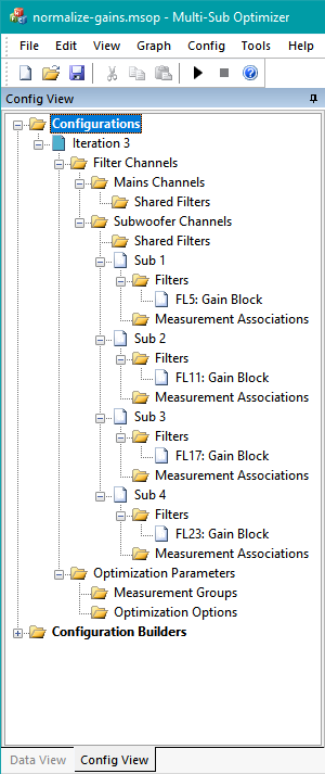
When you open up normalize-gains.msop, you'll see the stripped-down Config View as in the image below.
When you select each of the filters FL5, FL11, FL17 and FL23, you can view and change their properties in the Properties Window on the right side of the MSO main window. These properties were captured and are gathered and shown below.
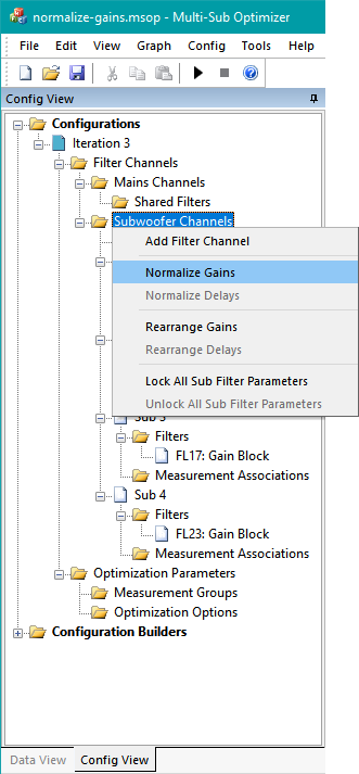
Right-click the Subwoofer Channels node in the Config View and choose Normalize Gains per the image below.
After normalizing the gains, the Config View will look like the figure below.
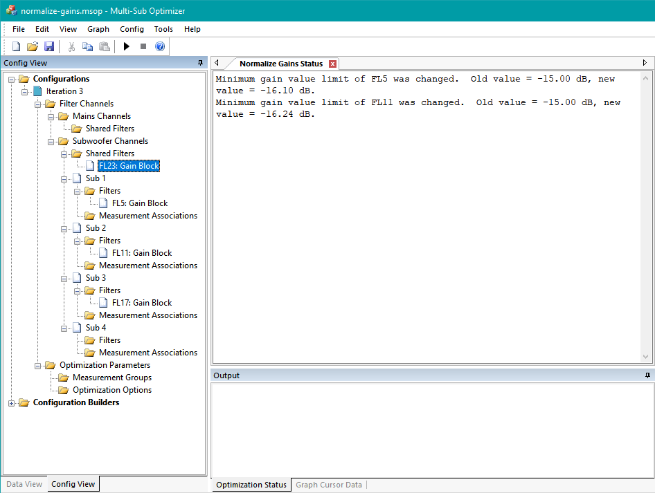
A few things are noteworthy in this figure. First, FL23 has moved from its position in the Sub 4 channel into the shared sub channel. Second, there is an information message from MSO stating that the minimum gain value limits for FL5 and FL11 have been changed. Both of these gain blocks had a lower gain limit of -15.0 dB prior to the normalization. The normalization has performed calculations to obtain new gain values for FL5, FL11, FL17 and FL23, just as previously described in the text surrounding the Gain Values Before Increasing Sub Trim and Gain Values After Increasing Sub Trim tables. In the case of FL5 and FL11, these new calculated values exceeded the old allowable range for gain limits, so MSO had to adjust the gain limits for the newly-calculated gain values to be legal.
What are the newly-calculated gain values for FL5, FL11, FL17 and FL23? Selecting each one to look at the parameter values and limits in the Properties window and combining them yields the following results.
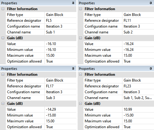
Compare these newly-calculated gain values in the figure above with the gain values listed in the Gain Values After Increasing Sub Trim table. You can see that the FL5, FL11 and FL17 gain values are exactly the same between the two. The gain block FL23 has been moved from its position in the Sub 4 channel to the shared sub channel, where it now assumes the role of Sub trim increase in the Gain Values After Increasing Sub Trim table.
What has the Normalize Gains Command Accomplished?
We are now in a position to solve the problem we discovered after running the filter report. The gains of Sub 1, Sub 2 and Sub 3 are very low compared to Sub 4. We'll introduce a new term that will help us understand why the Normalize Gains command will help us.
Let's call the sub that ends up with the highest gain the "reference sub". We can then summarize what we've experienced as follows.
- Running the optimization with a gain block for each sub (as established by the Configuration Wizard) has identified the reference sub. All the other subs have gains less than the reference sub.
- Performing a Normalize Gains command removes the gain block from the channel containing the reference sub and places it in the shared sub channel.
- This means that the gain value in each gain block of the remaining non-reference subs now represents the relative gain of that sub compared to the reference sub.
- This allows us to directly constrain the gains of the non-reference subs relative to the reference by setting the Minimum value and Maximum value for the allowable gains of each of the non-reference subs to some appropriate number.
- For example, if we wanted to force the gains of the non-reference subs so that in the worst case they'd be 10 dB less than the reference sub, we would set the Maximum value for each non-reference sub gain to 0.0 dB, and the Minimum value for each non-reference sub gain to -10.0 dB.
- The next topic will show how this is done.
Before Closing the normalize-gains.msop Project
Since the normalize-gains.msop project is still open, let's just do a very brief demonstration of another command related to Normalize Gains. That command is called Rearrange Gains. Right-click the Subwoofer Channels node in the Config View and choose Rearrange Gains. The gain blocks FL5, FL11, FL17 and FL23 are now back to where they were, and have gotten their original gain values back. Each time you invoke Rearrange Gains, it swaps the arrangement of gain blocks back and forth between the normalized and un-normalized conditions. This is useful if you accidentally normalize the gains and want to get back to where you were.
Applying What We've Learned
In the next section, we'll apply what we've learned about the Normalize Gains command to fix the sub gain mismatch problem in the Iteration 3 configuration. Then, once that is fixed, we'll look at gathering the data for entry into the miniDSP 2x4 HD.