Mid-Bass Module Integration Using a New Shelving Filter
The Problem
From time to time, discussions crop up in online audio forums regarding mid-bass modules. Although the term isn't strictly defined, I'll assume that such modules have the following properties:
- They are low-pass filtered but not bass-managed. That is, they play bass from only the single channel with which they are associated.
- The cutoff frequency of their low-pass filter is somewhere between 100-200 Hz.
- The frequency ranges of a mid-bass module and the main speaker with which it is associated overlap by a considerable amount.
- One purpose of such modules is to smooth out the Allison Effect interaction with nearby room boundaries at the upper end of the modal frequency response region.
By assumption, the mid-bass modules have a low-pass filter applied to them. But since the main speakers and mid-bass modules have a substantial frequency range over which they overlap, it's not immediately obvious what the corresponding filter for the main speakers should be to obtain a nominally flat response for the summation of the two. One might picture something similar to a two-and-a-half-way speaker, in which one of the two low-frequency drivers has a low-pass filter that combines with a 6 dB low-frequency shelf caused by the baffle step effect to produce a nominally flat combined response. This is illustrated nicely at Phil Bamberg's site. So it seems we need a shelving filter for the main speakers having a gain of 0 dB at high frequencies and a gain of -6 dB at low frequencies. In the two-and-a-half-way case, this requires that the low-pass filter of the ".5" woofer have a 6 dB/oct slope. It would be nice if we could find an approach that uses a steeper slope for the low-pass. That's one purpose of this article.
In the following steps, I'll develop filter transfer functions for the mid-bass module and main speakers such that a comparatively steep slope can be used for the low-pass filter of the mid-bass modules, in combination with a shelving filter for the main speakers, the sum of which has a flat magnitude response. Although I don't consider this to be the be-all and end-all solution, it is at least logical and could be a good starting point for actual setups that must be tweaked according to measurements regardless.
Review of Linkwitz-Riley Crossovers
In the formulas that follow, I'll use the normalized complex frequency variable sn, where
| (1) |
and ω0 = 2π times the cutoff frequency of the mid-bass module's low-pass filter.
The fourth-order Linkwitz-Riley low-pass and high-pass filters hav the transfer functions HL(s) and HH(s) respectively, where
| (2) |
and
| (3) |
The sum of HL(s) and HH(s) is the all-pass filter HA(s), where
| (4) |
It's not obvious that HA(s) is an all-pass filter, as all-pass filters have a transfer function of the form P(-s) / P(s), where P(s) is a polynomial in s. To see that HA(s) is an all-pass filter, we can factor its numerator into the product of two quadratic polynomials. This gives the following result.
| (5) | |
Finding the Shelving Filter
Let's rewrite HA(s) of equation (4) as follows:
| (6) |
where 0 < k < 1. This suggests that we might write HA(s) as the sum of a low-pass filter HLM(s) with a DC gain of k, and a low-frequency shelving filter HS(s) having a DC gain of 1 - k and a high-frequency gain of 1. That is:
| (7) |
where
| (8) |
and
| (9) |
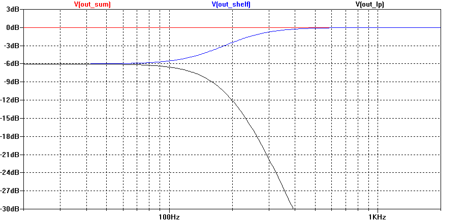
So now we have a fourth-order low-pass filter and a corresponding fourth-order shelving filter, and their summation is an all-pass filter. For k = one-half, each one will have a gain of one-half at DC. I call HS(s) a "fourth-order Linkwitz-Riley shelving filter". The low-pass and shelving responses are plotted below in figure 1 for k = one-half. It also shows the two filters summing to a flat magnitude response.
Most IIR DSP equalizers have the ability to realize HLM(s), but HS(s) would need to be realized using custom biquad programming. In order to do that, we'll need to factor HS(s) into the product of two second-order filters. After a bit of algebra, we get:
| (10) |
Having factored HS(s) in this way, one can apply the bilinear transformation to each of the quadratic factors of equation (10) to determine the coefficients of each custom biquad IIR filter.